High-resolution ADCs — an overview
The dramatic reduction in the cost of high-resolution ADCs brings a number of benefits to designers
BY STEVE GROSSMAN
Designers engaged in industrial and data-acquisition projects are likely to confront some of these analog-to-digital conversion issues:
• Digitizing an input signal that extends over a very wide dynamic range, such as delivered by an environmental sound pressure meter able to detect signals over a 60 to 80-dB signal range.
• Accommodating signals from different sources that exhibit quite different signal ranges.
• Resolving small changes around a certain value, so that the objective would be to expand the range around that point.
If a relatively low-resolution ADC is used, say with 10 bits of effective resolution, the high-level signal resolution would be close to 10 bits. However, for the low-level signals, if they are less than 10% of full scale, effective resolution might be no more than 6 or 7 bits. So in many cases, 10 bits equivalent to 0.1% would suffice for a sensor with an accuracy of only 1%. However, for lower-level signals, the effective resolution might be less than 1%.
Approaches to Design issues
There are a number of ways to approach these design issues, but the three primary ones are as follows:
• Connect a programmable-gain amplifier (PGA) in front of a relatively lower-resolution ADC.
• Apply the input signals to buffer amplifiers connected ahead of the ADC.
•Use a high-resolution ADC.
Let’s evaluate these approaches one at a time.
The PGA approach
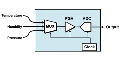
Historically, the PGA approach has been popular largely because, when paired with lower-cost ADCs, it winds up being less costly than higher-resolution ADCs. This approach is particularly useful if all of the input signals are near 0V, but cover wide dynamic ranges. Figure 1 is a simplified schematic of an ADC with a built-in PGA.

Fig. 1. Simplified schematic of ADC with built-in PGA.
This might be the case in a process control system that is monitoring signals from a variety of sensors that have different ranges, such as sound pressure meters. If gain-ranging is used on a wide-dynamic range signal, the key error that can show up is “crossover mismatch.”
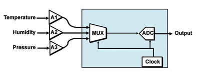
This means that when the PGA switches to a different gain value, the digitized output may jump a little up or down at that point. Therefore the gains must be carefully matched at each level to reduce that effect. This issue is of less importance when multiplexing signals from different signal sources. However, it depends on whether the system is designed with a fixed gain for each signal, as depicted in Fig. 2, or has dynamic gain-switching as would be the case with wide-ranging single inputs.
The issues with the gain-ranging approach are these:
Even though you may be driving a 12-bit ADC, if you put an amplifier ahead of it with a gain of 27 = 128, the effective input noise and offset voltage of the amplifier must be essentially 18-bit accurate. This would be a problem using a fixed-gain op amp, and an even more severe problem with a PGA that must be switched. So you have moved the accuracy requirement from the ADC to the PGA, without any benefit.

Fig. 2. Simplified schematic of ADC with independent outboard buffer amplifiers.
• You must know something about the signal in order to switch the gain. The overrange output of the ADC can be used for this, in conjunction with software, or you can do it with comparators. The process is messy, and the switching time can be a problem. (Perhaps you remember the old gain-ranging DVMs and how slow they were when they changed ranges!)
• A simple analysis could be performed on a precision low-noise op amp at a gain of 128: Calculate the effective output noise and offset voltage and compare it to an LSB of a low-resolution ADC. However, the linearity of the op amp in a high-gain mode could be a problem.
Information on designing PGAs with discrete components can be found in Ref. 1.
The multiple-buffer-amplifier approach
The multiple-buffer-amplifier approach may be used if the sensors or signal sources are at some distance from the data acquisition unit containing the ADC (see Fig. 2 ).
A single high-resolution ADC
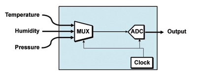
What is attractive about a single high-resolution ADC is its simplicity (see Fig. 3 ). If a 16-bit ADC is used, losing 3, 4, or 5 bits to a smaller-dynamic-range signal reduces the effective resolution of that signal to 11 to 14 bits. However, this is still sufficient for the accuracy of most transducers, because the ADC’s accuracy is on the order of 0.05% or better.
Since the prices of these devices have recently dropped into the $5 or below region, cost will seldom be a factor. If higher effective resolution is needed, or a wider dynamic range needs to be accommodated, ADCs in the 18-to-24-bit range can be used and still provide cost-effective performance as well as a much simpler system.

Fig. 3. Simplified schematic of a single high-resolution ADC.
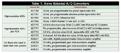
Using a high-resolution ADC is pretty clearly the design choice for resolving a small change in a signal around a certain point off zero. This is an alternative to what has also be accomplished by using a digital-to-analog converter (DAC) to offset most of the signal. This is still a viable choice for some situations. One popular PGA that could be used for the gain-ranging approach is the AD8250 (see Ref. 2). A number of ADCs are listed in Table 1 . ■
References
1.”Basic Linear Design,” Chapter 2, Section 2.13. www.analog.com/library/analogDialogue/archives/43-09/linear_circuit_design_handbook.html
2.”The AD 8250 Programmable Gain Amplifier,” www.analog.com/en/amplifiers-and-comparators/instrumentation-amplifiers/ad8250/products/product.html
Table 1. Some Selected A/D Converters

Visit http://ADCs.electronicproducts.com to see full coverage of High-resolution, analog-to-digital conversion circuits and the benefits of designing with them from Analog Devices. Innovation, performance, and excellence are the cultural pillars on which Analog Devices has built one of the longest standing, highest growth companies within the technology sector. Acknowledged industry-wide as the world leader in data conversion and signal conditioning technology, Analog Devices serves over 60,000 customers, representing virtually all types of electronic equipment. Celebrating over 40 years as a leading global manufacturer of high-performance integrated circuits used in analog and digital signal processing applications, Analog Devices is headquartered in Norwood, Massachusetts, with design and manufacturing facilities throughout the world. Analog Devices’ common stock is listed on the New York Stock Exchange under the ticker “ADI” and is included in the S&P 500 Index. Visit us at http://www.analog.com
Sponsored by Analog Devices
Advertisement
Learn more about Analog Devices


