High-speed DACs directly convert to GHz and beyond
Technology advances allows significant changes in the way that microwave communications systems are designed
by A. Glascott-Jones, N. Chantier, F. Boré, M. Wingender, J.P. Amblard, E. Marcelot, and B. Righter, E2v, Grenoble, France
www.e2v.com
Broadband communications performance requirements continue to push the limits of analog-based technical solutions. And, with further system considerations — such as flexibility in the face of evolving modulation standards and power consumption issues — the ability to implement multichannel solutions completely in the digital domain becomes highly attractive.
Technology advances in high-peed digital-to-analog data converters are allowing significant changes in the way that microwave communications systems are designed. The ability of the new generation of digital-to-analog converters (DACs) to convert from a digital signal directly into L, S, or even C band (6 GHz) can be seen as a large leap in capability, allowing greater system flexibility and reduction in power consumption. Multiple up-mixers that would normally have been required can now be deleted, along with the VCO/PLL jitter, which adds at every up-conversion. The high performance of these DACs can also be employed at slightly lower frequencies in cable drive applications such as highlighted by the DOCSIS standard.
In addition, with rise times of 60 ps, the application of these DACs in automatic test equipment for high-speed digital components would be highly beneficial. This article covers the performances of the new generation of DACs along with the techniques used to extend the range to higher frequencies.
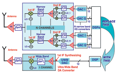
Currently, modems employ a mixed analog/digital architecture requiring mixers for up conversion. The use of high performance DACs allows the replacement of a large number of these converters by a single DAC as shown in Fig. 1 .

Fig. 1: Broadband modem with and without microwave conversion DAC.
Up conversion in the digital domain
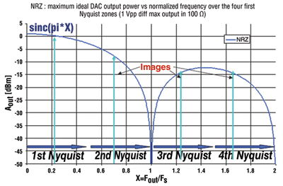
For up conversion using microwave DACs, the effect of aliasing becomes an aid rather than a hindrance. The diagram below shows the aliases of a 100-MHz signal when output from a microwave DAC using a sampling frequency of 3 Gsamples/s. The solid curve shows the sinc x response typical of a DAC using a non-return-to-zero (NRZ) coding with a zero at the sampling rate. The signal at ~0.2 Fo/Fs is readily apparent in the first Nyquist zone but also the alias appears in the second Nyquist zone and images will also appear in the third and fourth zones. Appropriate filtering around the frequencies of interest is all that is needed to isolate the required frequency.
Expectations for a µwave DAC
The challenge for DAC designers is to extend the DAC performance into these higher Nyquist zones. The challenge for the baseband system designers is to develop techniques whereby the bandwidth of the up converted signal is not limited by the Nyquist rate of the digital processing system (FPGA or DSP). Developments here include polyphase filters where multiple digital oscillator blocks are used – each set to a different phase. In this way, baseband techniques are able to match developments in the DAC itself. Other developments in the DAC include novel and innovative forms of coding which extend performance to the higher Nyquist zones.

Fig. 2: DAC sinc response. The diagram below shows the effect on the response of using these different coding schemes—which include NRZ, return to zero (RTZ) and an RF mode—where consecutive samples are inverted. In addition to these, another mode, Narrow Return to Zero (NRTZ) has been shown to provide extremely good performance in the first and second Nyquist zones.

Fig. 3: Comparison of response for different coding schemes.
Critical parameters for these “direct microwave synthesizing” DACs include:
Bandwidth: The bandwidth of the device should be greater than 5 GHz to provide performance in third and fourth Nyquist zones;
Bandflatness: A flatness of better than 0.5 dB over the full range is important in I/Q applications;
Spurious-free dynamic range (SFDR): The production of spurious harmonics should be minimized in some cases to better than 70 dBc.
Clock-related spurs: A ny clock-related spurs have to be minimized (Fc;Fc/2,Fc/4) to better than 80 dB.
Update rate: A higher update rate will mean larger Nyquist zones, however the component’s bandwidth should also be taken into account for applications using 3rd Nyquist zone and higher.
Noise floor: Typical noise floors require around 150 dBm/Hz for GSM systems.
Applications
Cable drive systems
Data Over Cable Service Interface Specification (DOCSIS) system designers require modulators which provide the combination of:
a. Nyquist zones well in excess of 1 GHz,
b. High linearity and flat frequency response between 50 MHz and 1 GHz of output frequency.
c. High dynamic range of 12 bits or more.
d. Low H2 and H3 harmonics and low noise floor.
e. High adjacent channel isolation at any center frequency between 50 and 950 MHz Fout.
The DOSCIS specification is particularly exacting, mainly due to the requirement to support analog video, and requires an adjacent channel power of better than 73dBc.
The diagram below shows the example of a DOCSIS 128 QAMpattern.

Fig. 4: DOCSIS pattern using 100-MHz center carrier.
Gigabit passive optical network (GPON) applications
GPON systems for optical fiber communication using 16 QAM mapping, polarization division multiplexing, and four bands need data converters sampling in the range of 3 Gsamples with 10-bit dynamic range and high linearity.
Automatic test equipment (ATE) applications
Manufacturers of Automated Test Equipment are confronted with the challenge of designing Software Defined Signal generators with superior performance compared to the device under test.
Memory testers in particular need to generate stimulus signals with a complex variety of rise time and fall time edges with different Voltage levels for low and high states. RF testers need to generate complex UWB patterns which can be centered at high GHz frequencies; the performance of these testers is often limited by their digital to analog conversion block.Step responses required to be able to test the latest semiconductor components should be better than 60ps which implies bandwidths approaching 6 GHz.
Frequency-hopping encryption systems
Systems such as wireless military datalinks need to be able to make the largest possible frequency hops and still maintain a high dynamic range to accommodate for high QAM factor modulation. A wide-bandwidth converter enables almost instantaneous transfer of carrier frequency.
Communication satellites
Future generations of digital payloads need to be more flexible in the frequency domain (the Transparent Processor concept). They also need to accommodate for larger instantaneous bandwidth so to fit more FDM channels per hardware channels. Additionally, they need to reduce their overall power consumption and to reduce the complexity and size of RF circuitry. But, many of these payload systems will still use digital processing chips with IO speeds that are limited in the area 375 Mbits/s.
So components should be able to provide flexible input interfaces with multiplexer ratios of up to 4:1. Other features that extend output performance into the higher Nyquist zones are dedicated under-clocking interfaces where the output sample rate is maintained at maximum while the input rate is reduced. This enables the response into the upper Nyquist zones to be improved. A space-qualified component is obviously required in these cases.
Military electronic warfare systems
Military EW systems need to generate a wide range of complex RF signals over large instantaneous bandwidths which can exceed 1GHz and which are positioned at microwave frequencies.
Designers of these systems are constantly looking for DACs which provide not only Nyquist zones larger than 1 GHz, but which also offer flat frequency response in these large instantaneous bandwidths. And, in addition they should also generate these signals with a center frequency positioned in the microwave frequency range. Good SFDR performance is essential to improve jammer detection. Designers of Military EW systems also need the shortest possible latency, fewer than four clock cycles is ideal.
All the applications mentioned above would benefit greatly from the use of complete direct conversion transceivers and their inherent advantages of fewer components, less power consumption, lower cost, more flexibility, and smaller size. There are a small number of components that offer this capability and even fewer can truly claim that they offer “Direct Microwave Synthesis.” For example, e2v’s latest MUXDAC, EV12DS130A, is one of these. ■
Related Products: Data Acquisition
Advertisement
Learn more about e2v technologies


