Highly isolated power supplies for medical applications
To achieve a low common-mode noise on the output a power supply requires a thoughtful analysis of the component and parasitic capacitances between the primary and secondary
BY LORENZO CIVIDINO
SL Power Electronics
www.slpower.com
Industrial and medical instruments operate in a noisy environment and are prone to interference from common-mode noise present as a result of a lack of knowledge or understanding of the inference mechanisms.
Electronic sensors used in industrial and medical applications may have very high impedance and low immunity to common-mode noise. Isolating the sensors and the electronic device connected to the sensors can be a challenge. The common-mode noise can introduce errors in the device reading or in a worst-case scenario render them ineffective. A significant source of ac line frequency common-mode noise can be through the isolating power supply. Although much attention is placed on high-frequency noise sources and mitigation, line frequency common-mode noise is an issue with some patient-monitoring devices. It’s important to understand that conducted and radiated paths in a power supply that contribute to the ac mains common-mode noise in applications requiring low leakage current for patient protection while powering sensitive electronics with very-high-impedance circuits.
Noise coupling
A typical power supply consists of an ac/dc-rectification stage followed by a high-frequency dc/dc stage and control circuitry to regulate the output voltage. High-frequency filtering is well understood and routinely a part of the product design.
Output common-mode noise is often overlooked and not specified. Most of the attention is in the input EMI filter and output differential noise filtering. There is though, significant output common-mode noise present due to conductive and radiated coupling to the output. In most applications this is not an issue as the output is grounded either internally at the power supply or at the end application or significant capacitance to ground is added on the output to earth ground. However, in medical applications there are stringent patient leakage current requirements which limit the amount of output to ground capacitance that can be used. For example, IEC60601-1 limits the amount of patient leakage current to 50 µA under single fault conditions. The fault condition implies the patient is at a line potential due to a fault in another applied instrument or device and hence is at risk of electrical shock and harm if there is a path to ground.
Patient-monitoring equipment can be sensitive to common-mode noise do to the nature of the monitoring device. The sensors have very high impedance, and the high-impedance high-gain amplifiers can malfunction in the presence of common-mode noise.
It may be surprising to realize the output of a power supply can have very significant ac-line frequency noise. This manifests through capacitive coupling through isolating components such as transformers, optocouplers, RF noise-filtering capacitors, and through proximity of circuitry alone. Table 1 shows common values of parasitic capacitance in devices used in a low-power switch-mode power supply.
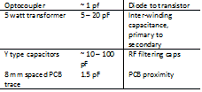
Table 1: Component and parasitic capacitance
Figure 1 shows the schematic of a typical Class II input low-power switching power supply. The parasitic components have been added in Fig. 2 to illustrate the physical location of the parasitics.
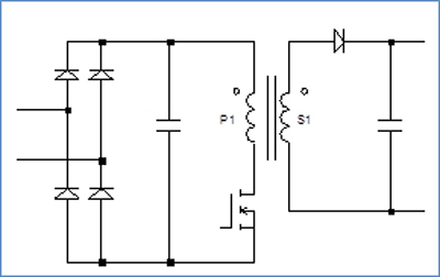
Fig. 1: Simplified off-line flyback power supply.
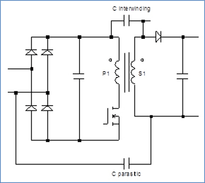
Fig. 2: Same power supply with some parasitic elements shown.
Analyzing noise using a circuit simulation tool, one can see the significance of the unintended capacitance of the bridging components. The output common-mode noise is ~28 Vp-p when the maximum input voltage, 265 Vac, is applied to the power supply as shown in Fig. 3 . Considering the target common-mode noise for the output to ground is
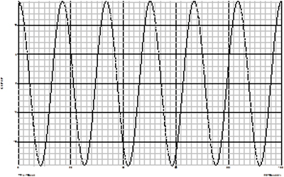
Fig. 3: Output common-mode noise of ~28 Vp-p with an ungrounded output with ~10-pF primary to secondary capacitance and ~10-MΩ output to ground impedance.
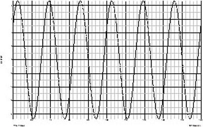
Fig. 4: Output common-mode noise, ~17 Vp-p with 10-pF primary to secondary capacitance and 330-pF output to ground capacitance measured with 10-MΩ probe.
Having a ground reference point helps reduce the output common-mode noise but will increase the patient leakage current during a fault condition. Allowing for parasitic leakage currents from cables and a safety margin to remain below the 50-µA leakage current requirement, one is limited to approximately 200 to 300 pF. Even using 330 pF, the output common-mode noise is ~17 Vp-p as shown in Fig. 4 . Lowering the primary to secondary capacitance will further help, but we’re approaching a point of diminishing returns due to practical limitations, proximity of components and near field dv/dt coupling.
Proposed solution
A novel approach is to use a second isolating transformer to allow a clean ground reference while also providing a floating output as shown in Fig. 5 . Interestingly, output filter capacitance is still needed due to line frequency noise pick-up from internal power supply fields and stray capacitance as well as external environmental sources such as lighting and other electrical equipment. However, line-frequency output common-mode noise below 1 V is achievable with careful PCB layout and mechanical design.
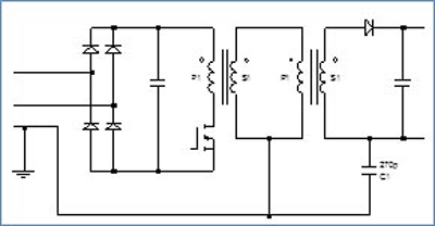
Fig. 5: Two transformer design reduces common-mode coupling. Note: The techniques described herein may be protected by a pending patent application owned by SL Power Electronics Corporation
Care must be taken in spacing input and output leads and traces to prevent E-field coupling to less than 1-pF levels. Figure 6 shows the actual output common-mode noise measured at 265 Vac.
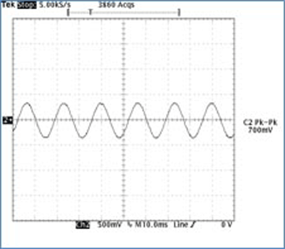
Fig. 6: Output common-mode noise measured using the dual transformer approach along with careful design to mitigate capacitive and E-field coupling.
Achieving low common-mode noise on the output of an ac/dc power supply requires a thoughtful analysis of the component and parasitic capacitances between primary and secondary, a clear understanding of the practical limitation in minimizing capacitive and dv/dt-coupling from the line side to the isolated secondary circuitry, and a strategy to mitigate the coupling. The proposed dual isolation transformer making use of a Class I input is an effective solution in realizing a low-noise floating output with low earth leakage current. ■
Advertisement
Learn more about SL Power


