As silicon fabrication technologies used to construct ICs — microprocessors, FPGAs, or special-function devices such as network or communications processors — have gone from generation to generation, the number of transistors has grown ever-larger, the individual devices have grown smaller, and the operating voltage they can tolerate has diminished. The core voltage that such a chip runs at today may be less than 1 V; 0.9 V is commonplace.
So, when you are designing the final stages of a power system that will satisfy the demands of the latest ICs on a high-density circuit board, the performance of your point-of-load (POL) dc/dc converter will be critical to the performance of the entire board, and system.
And while individual transistors in today’s most advanced ICs may use less power, there are millions more of them. As a consequence, design engineers have struggled to keep power consumption in check.

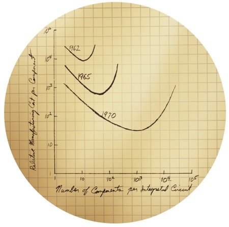
Fig. 1: Today’s transistors may be significantly more efficient but the number has improved in line with Moore’s Law and power consumption is increasing. (Courtesy Intel)
The peak power requirement of a processor reveals a lot. It is, in effect, the maximum power you might ever need to feed such a chip, and figures of 100 W or more are not uncommon. Considering that today’s core voltages are hovering around 1 V or lower, current ratings are moving to 100 A and beyond. This fact is worth dwelling on because it is in those figures, compounded by the energy-saving tricks built into the latest ICs, that performance of the PoL module becomes extremely critical.
To cut average power usage, the chip designer will arrange to switch off anything that's not being used at any given moment, in response to processing load. In a multicore processor, any or all of the cores might be shut down or restarted at any time, meaning tens of amps dropping to zero — or the reverse, in microseconds (or less). High dI/dt values are a design challenge in themselves; everything that they imply in terms of minimal inductance, carefully placed capacitance, and shortest track lengths is part of your basic toolkit as a power-rail designer.
Dc/dc converters powering the load must also deliver, not only in setting the correct supply voltage levels but also in achieving the correct transient behavior to respond to the demands of the fast-changing load. You can look at the PoL module as a control loop maintaining the set point of its fixed dc-output; or as an amplifier delivering a fixed level but with a wide frequency response. An over-damped control response will mean that when your microprocessor suddenly demands more current, voltage levels will sag, and logic values may be lost. In the other direction, the regulator will “spike” above line voltage and will ring or oscillate. Circuitry may be damaged, or conducted interference from the unwanted transients may also corrupt logic levels. In all circumstances, your regulator must be stable.
Conventionally, this has been the space where the analog power supply engineer has been at home. Their skill is to arrange for the circuit to have high gain at dc, and apply standard control-loop techniques to place poles and zeros in the loop’s response so it responds to step-changes in load rapidly, but without “ringing,” and remains stable under all load conditions. They might analyze their circuit from first principles to determine its gain/phase response profile; or they might measure it with a network analyzer; or in less demanding cases they might reach a solution empirically. All are classic analog-design territory.

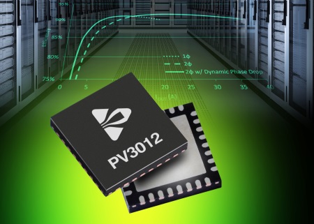
Fig. 2: Digital power ICs, such as Powervation’s PV3012 give real time adaptive loop compensation
Digital power offers you an alternative approach. In the digital version of the regulation loop, a fast analog-to-digital converter samples a representation of the output voltage, a DSP core runs algorithms in software that implement the chosen control loop, generating waveforms to drive pulse-width-modulated (PWM) outputs to directly control the power switches, typically MOSFETs. You can set the parameters and filter coefficients in an advanced algorithm, and you will guarantee all that is needed in terms of regulation and stability. Conversely, with the more advanced digital VR controllers the compensation is set by the VR controller itself. You need a relatively fast and powerful MCU or DSP core to carry out the processing, but that is not a large cost in today’s silicon technology.
When you turn to a digital control loop you get a range of other benefits. All of the “secondary” PSU functions (taking delivery of stable voltage to be the primary role) such as sequencing, ramping, margining, fault response and reporting of voltage, current and status, and external control, become exercises in software. Your system communicates with the digital power component via the power management bus (PMBus); you can get a measure of the extra flexibility by considering the specification sheet of a digital voltage regulator IC. The list of PMBus commands (VOUT mode/command/trim — and so on) will comprise at least 10 entries; and for time-related commands (delay, rise time, fall time) there will be approximately five commands; overall there will be well over 100 commands in the set.
Ask any system designer if he or she would like that degree of control and flexibility and the answer will undoubtedly be “yes.” But that enthusiasm has not been reflected in the adoption of digital power technology in the broad market, and the full range of digital power functions has only been put to use in large, connected systems such as telecoms or network infrastructure racks.
An analog PoL will struggle to address the complex power requirements of the latest chipsets. Both large and small OEMs are running into power requirement challenges on their board-level designs. So, how do you bridge the divide? First of all we have to realize that there is a wide spectrum of reasons why the industry has only been slowly adopting digital voltage regulators.
At one end lie smaller projects that have less of a need for system-level control; whose analog designers have the skills to configure a stable control loop with resistors, capacitors and gain settings but fear that they will need the corresponding expertise in writing software or code for DSPs. They may also wrongly believe that their microcontroller software coders will need to dust off their old text books since they haven’t implemented control theory and Nyquist criteria since college.
At the other end lie major OEMs, who have the capabilities to deliver fully digital systems for new designs, but perceive that the cost and complexity of adding digital power to existing systems is prohibitive.
So what can you do when you want to leverage some of the most compelling benefits of digital power but you don’t want to implement a full system bus?
At CUI, we’ve addressed this dilemma by taking a no-bus approach – that is, to let system architects benefit from efficiency gains, transient response benefits, and auto-compensation advantages inherent in digital power without incorporating a digital bus communication into their system.
During the development cycle, users can dynamically test and manipulate the desired functions within their system, monitor the results, and set the desired fault management functions. In production, the engineering header is pulled and the specified parameters are loaded into the module by CUI based on the customer’s specific requirement. Once downloaded to the module, any further connection to the bus is no longer required; the upshot is that the module exceeds the performance of an analog POL module while occupying the same footprint.

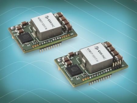
Fig. 3: Digital PoLs, such as CUI’s Novum range, give a voltage accuracy of 1% and provides leading transient response characteristics.
But prioritizing ease of use doesn't mean sacrificing performance. The NSM2P delivers industry-leading performance intended to address the most challenging needs of today’s advanced ICs. Leveraging the digital control loop, the series delivers 93% efficiency at 50% load, features voltage accuracy of 1%, and provides superior transient response characteristics. But perhaps the greatest benefit designed into the NSM2P series is automatic compensation. Auto-compensation enables the module to dynamically set optimum stability in real time as conditions change. It eliminates the need for manual loop compensation, one of the most labor-intensive, time-consuming aspects of analog power design, and the need to build in margins for component aging, manufacturing variations, temperature and other factors. The realized benefits for the project manager include improved performance, faster time to market and lower overall cost.
And, just as the digital module can be selectively employed to introduce digital concepts initially where they are most needed, you can also start to use its more advanced functions as you recognize the benefits in them or switch to CUI’s other Novum Advanced Power POLs, the NDM2P and NDM2Z series, and open up the entire suite of digital features.
The increasing complexity of processors caused by Moore’s Law means that analog techniques are rapidly becoming unsuitable for power supplies. But, for some this means rapidly learning — or buying in — the necessary skills. And for others it means adding complexity to a design when all that’s needed is a small subset of features.
New devices, such as our Novum NSM2P No-Bus PoLs are simplifying digital power design, allowing small and large OEMs alike to access features such as auto-compensation in a package that is higher performing and easier to implement than an analog device.
So, what do you do when you only want the best features of digital power and don’t need to implement a full system bus? Simple, get rid of the bus.
Advertisement
Learn more about CUI Inc


