Tired of obnoxious neighbors blaring obnoxious music to obnoxiously keep you up at night? Yes, me too; so much so, that I sometimes fantasy about firing an RPG into their apartment and permanently ending their midnight crescendo. Of course, I’m the sensible and sane sort who’d never resort to violence, so instead, I’d rather set off an electro-magnetic pulse right outside their window.
The electro-magnetic pulse generator, or EMP generator, is a device capable of generating a transient electromagnetic disturbance that radiates outward from its epicenter, disrupting electronic devices (or frying, depending on its capacity). Some EMP bursts are naturally occurring, such as electrostatic discharge (ESD), where others, such as the nuclear electromagnetic pulse (NEMP), are man-made.
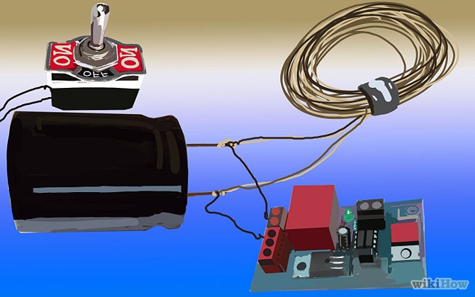
The following step-by-step guide documents how to construct a rudimentary EMP generator using commonly available items: Soldering iron, solder, disposable camera, small toggle button, insulated thick copper cable, enamel-coated wire, and a high-current momentary switch.
Disclaimer: EMP’s are dangerous and should not be operated near medical or computer equipment; avoid this at all costs if you wear a pacemaker. Also — neither I, nor Electronic Products, encourage you to use the EMP for the destruction of property. We do not condone illegal behavior.
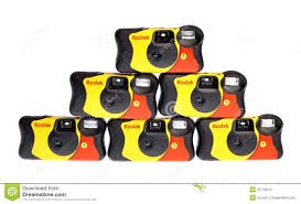
Step 1: Obtain a disposable point-and-shot camera
Purchase a cheap disposable camera such as the Kodak variety sold at the local drug store.
Step 2: Put on a pair of rubber gloves and open up
Don your rubber gloves to avoid the possibility of receiving a painful shock when opening up the camera; its flash capacitor carries 330 volts or so, when fully charged.
Step 3: Open the frame and locate the large electrolytic capacitor
Using the flat end of a screwdriver, pry open the camera’s chassis while taking care to not damage the printed circuit board beneath. Once open, locate the large electrolytic capacitor — the black cylindrical looking component with two leads — and the PCB to which it’s attached. Bear in mind that the side of the capacitor with the markings represents the negative terminal.
Step 4: Test the flash capacitor’s charge
Grab a voltmeter, set it to the 1000-volt scale, and verify that the capacitor is discharged. If voltmeter cannot find a reading, the capacitor’s discharged and you can skip step 5.

Step 5: Discharge the flash
To discharge the capacitor we’ll first need to activate the flash by inserting batteries and film into the camera and turning on the flash. Next, we press the shoot button and immediately remove the batteries to prevent the capacitor from charging again. Use the voltmeter once again to ensure full discharge. If a residual charge persists, place a 100-ohm resistor across the leads. Some suggest using a screwdriver to discharge the capacitor, but I advise against this as this technique creates an ugly spark.
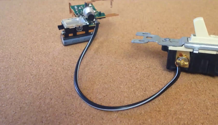
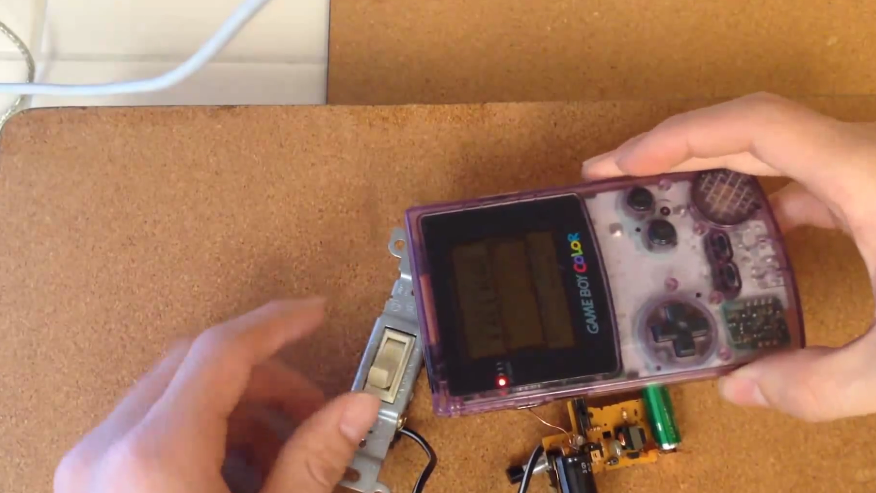
Step 6: Remove the PCB and replace its charge switch
Remove the capacitor’s PCB and find the on/off button. Peel this off and solder a push button in its place on top of the solder pads to reduce the risk of electric shock.
Step 7: Solder the capacitor
Solder two insulated copper cables onto the capacitor’s two terminals and wire one end to a high current momentary switch as shown below. The high current momentary switch can easily procured from the Internet. Leave the other end unattached for now.
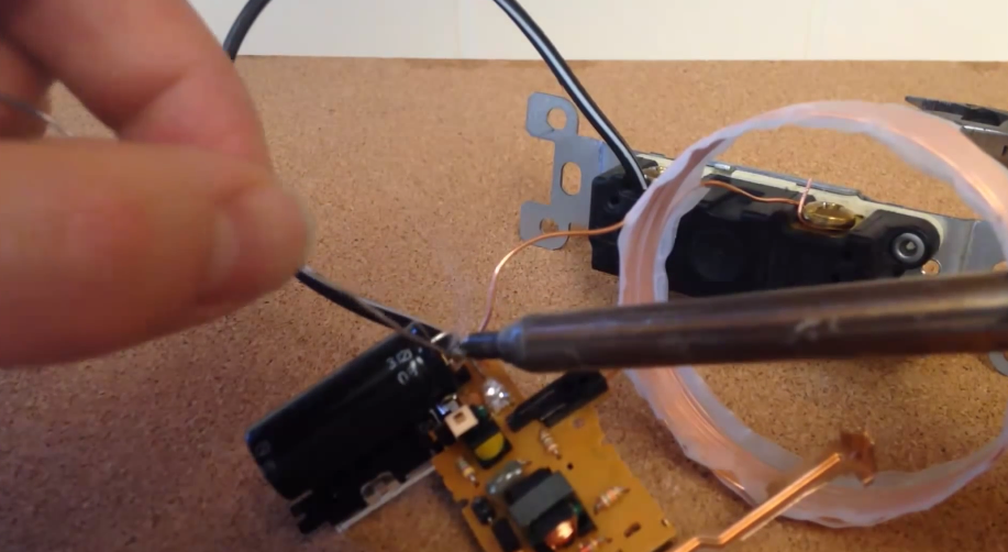
Step 8: Form the load coil
Wrap the enamel-coated wire 7 to 15 turns around a circular object with a diameter of 2 inches. Ensure the wire lines up precisely with no crease or overlap. Place double-sided tape around the diameter of the circular object to help with this.
Once you’ve created a satisfactorily thick loop, remove the object. Now bind the coil with adhesive tape but leave two protruding leads to connect the terminals. If you’ve an iron rod handy, you may slip it through the center of the coil to intensify the generated magnetic field.
Step 9: Connect coil and the switch
Use sandpaper to remove the enamel coating off the tips of the two wire leads protruding from the coil before attaching one to the other terminal of the capacitor. Next, attach the remaining lead to the ”on” side of the switch.
The end result will be a PCB with a switch to turn the charger circuit on and off along with a load coil that’s switched across the capacitor.
Disclaimer 2: This project is not powerful enough will not disrupt your obnoxious neighbors’ sound systems.
Step 10: Charge the EMP generator and fire
Simply re-insert the battery into the camera’s PCB to provide a power supply. When you’re ready to test out your creation, fetch the handheld electronic device you’d like to disrupt and flip the on switch. Do not simultaneously hold down the charge button while firing the pulse or you may damage the circuit.
Bonus
Experiment with different capacitor value and wire diameter for different results.
Source: WikiHow and Cameron Cobb
Related Content
Selecting EMP protection for enclosures
Electronic Products Word of the Week: Electromagnetic interference
Advertisement
Learn more about Electronic Products Magazine


