While the Web is full of DIY electronics projects, few are useful as they are entertaining. That’s not the case with this one here, however — a laser tripwire alarm system, which can be used to secure off-limit areas of the home and workplace.

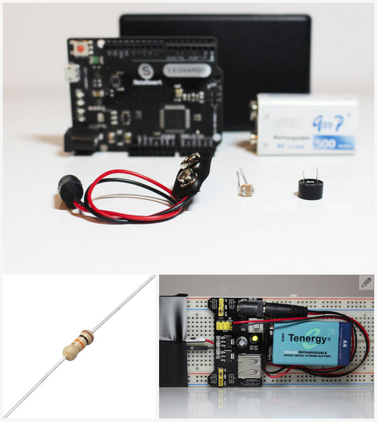
The project is fairly straightforward and can be completed in five steps and less than an hour’s time. To complete the project, you will need the following electronic parts and components:
• Development Board
• Junction Box
• Red Dot Laser Diode
• Buzzer
• Photoresistor
• 9V Battery
• Male-to-Female Breadboard Jumper Cable
To begin, you will need to hook up a soldering iron in order to make two horizontal holes on the junction box. The purpose in doing this is to create an area to house the photoresistor.
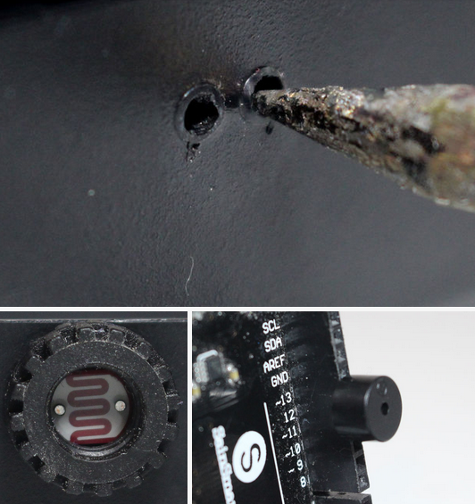
Thread the photoresistor through the junction box; when completed, glue a piece of plastic around it. Doing this makes it easier to calibrate the sensor in several different lighting conditions.
Worth pointing out in this step: the positive pin from the loudspeaker connects to pin 13 on the development board, while the negative pin connects to pin 11.
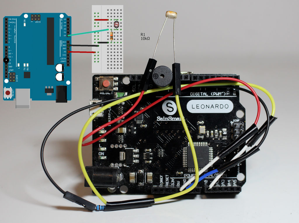
Now that that is all set up, we can begin wiring the laser tripwire alarm system. Begin by connecting the photoresistor to the 5V pin on the development board. The left-over pin connects to the analog 0 pin. Now go ahead and establish a connection between the analog 0 pin and the ground using a 10K resistor.
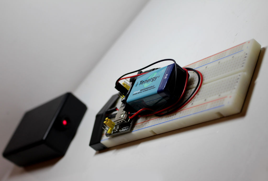
When completed, and before you place the 9V battery inside the enclosure, use some double sided tape to separate it from the development board.
You can now begin calibrating the sensor to the preferred setting in the room. When satisfied, upload the following code to the system:
int PR = 0; //Analog 0 to Photoresistor
int Loud = 13; //Pin 13 to Loudspeaker
void setup() {
pinMode(PR, INPUT); //Photoresistor is set as an input
pinMode(13, OUTPUT);
pinMode(11, OUTPUT);
Serial.begin(9600);//set serial monitor at 9600 baud
}
void loop() {
int Read = analogRead(PR);// “Read” reads analog0 data
Serial.println(Read);// Print that data
if (Read {
digitalWrite(Loud, HIGH); //speaker turns on
digitalWrite(11, LOW);
}
else //if the value is greater than 120
{
digitalWrite(Loud, LOW);// speaker will turn it off
digitalWrite(11, LOW);
}
delay(1000);//run every second
}
You’ll note this version is calibrated to work in low light conditions, as it’s placed close to the floor, and within a room not too far from a window.
Close the junction box and place it as you see fit.
To see a video demonstration of the project, check out the clip below:
Advertisement
Learn more about Electronic Products Magazine


