I find that I learn an immense amount of information by using examples — seeing how other people do things and understanding the “why” of their decision-making process. With this in mind, and by working with onlinecomponents.com, I built an Arduino Uno from scratch and, in a sense, reverse-engineered it so that I could share the experience. An Arduino Uno is a surprisingly simple board to construct, as exemplified in the below video, and its key to success lies in the simplicity of its interface — both hardware and software.
After downloading the Arduino Eagle files, sending the boards to be manufactured, and buying all of the required parts, I made a solder paste stencil from a laser cutter and overhead transparency. By lining up the stencil and board, I was able to apply solder paste to the spots on the board where I needed it to place parts for the Arduino Uno. As I was placing each part, I had to figure out what its purpose was. In some instances, this was blindingly obvious. In others, it provided an interesting solution that I hadn’t previously considered. To show you what I mean, let’s break it down by part.
First, we place the reset button, which is tied to the reset pin on the microcontroller, the ICSP programmer, and the reset pin in the headers. Next is a ferrite chip inductor, placed on the USB ground line to suppress high-frequency noise that could contaminate the overall ground for the board. Next is a diode, placed so that if the reset line for the USB microcontroller goes high, it will pull down the harmful voltages by conducting onto the 5-V line. There are actually two varistors on the board, attached to the two data lines of the USB, that help to keep the lines clean from excess voltage without affecting the data signals. Between the varistors is a 22-Ω resistor array, put in series with the data signals, to act as termination resistors. A PTC, or resettable fuse, is placed in series with the incoming power from the USB to trip if the board pulls too much current, protecting your computer's USB. There is also a PMOS transistor here that works, via an op-amp, as an indicator to the board of whether power is being provided via USB or through the DC power jack. Next are a couple of passive components — two of them are 22-puff caps for the crystal. A word of advice: some microcontrollers have these capacitors internally. However, if they don't and you don't have them, your microcontroller won't work.
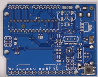
We then move over a bit and place a capacitor to clean up the analog reference signal, a yellow LED, followed by another resistor array that acts as the current limiters for the LEDs on the board. Next is an Atmega 16U2 that acts as a USB-to-serial converter and makes it so that you can simply hook up a USB to the board without worrying about an FTDI cable. The QFN is also one of the more difficult parts to solder because the pads are tiny and you need enough solder paste to make the connection, but not so much that it will bridge. The alignment, though, is relatively easy, as it will self-adjust during reflow to line up on the pads more exactly. We then place a few more status LEDs and passives used for power conditioning.
We then have a dual op-amp with one op-amp that acts as a buffer for a voltage divider that also controls the 3.3-V LDO, while the other op-amp controls the communication status LED. An LDO is placed that accepts the 7–12-V input via the barrel jack and drops it down to 5 V. This is directly followed by another LDO that drops the 5 V down to 3.3 V, the one controlled by the op-amp. We then have the 16-MHz ceramic resonator for the main microcontroller. This resonator has internal capacitors instead of the two external capacitors. While it isn't as precise, especially when compared to a crystal oscillator, it is quite small and inexpensive. Finally, on the other side of the board is an LED, resistor array, and protective diode to show the ICSP programming status and protect against transients on the power line. Another small power-cleaning capacitor is placed on the VCC pin of the microcontroller, before moving to the two large electrolytic capacitors. The first one I placed cleans up the 5-V power while the second one cleans up the incoming power from the barrel jack. Both caps are rated to 25 V and are completely interchangeable. The last surface-mount device is a final diode to make sure that there isn't any current flow back into the barrel jack.
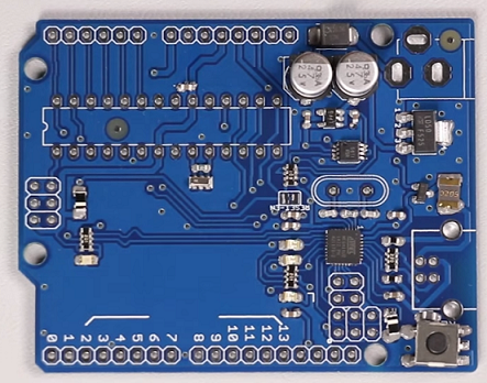
After the board spends time in the reflow oven, it’s time to finish up with the through-hole devices. First, we put on the 16-MHz crystal that the USB-to-serial microcontroller uses. Then, we add the socket that the DIP package microcontroller sits in, allowing you to switch out the microcontroller if something unfortunate happens to it. The headers are .1-in. pitch, but then they put odd gaps between some of the pins, which is supposedly an accident that has continued through the years because they want to keep all generations compatible. I find it heartening to see that I’m not the only person who makes mistakes. Finally, we add the USB and the power connector to complete the project.
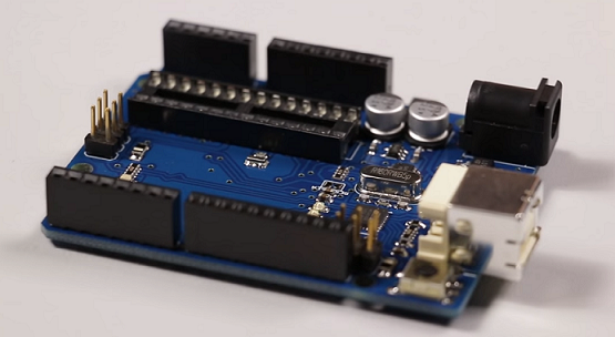
The time and effort to assemble a single board this way is non-trivial. However, it's a great way to learn more about the electronics that are out there and get some practice with prototyping assembly techniques.
For a complete list of parts required to assemble an Arduino Uno, please click here.
Advertisement
Learn more about Electronic Products Magazine


