What is a crossover cable used for?
The fastest way to connect PCs together, to a router or central switch, is through Ethernet cabling, a standard that’s been in networking installation for years. While you can opt to go wireless, those types of connections will typically be slower and are vulnerable to interference. A strong network connection goes for 100 m or more at gigabit speeds.
In an Ethernet networking scenario, such as a home with multiple PCs that are wired, the computers need to connect to a principal router. That router takes all the bits sent out by the computer and relays them onto additional devices in the network or out to the broader internet. With a cross-over cable, users can connect two devices directly without the need for a router in the middle.
The cable reverses the pins so that the output on one computer is sent to the input of another. And while connecting two machines is one practice of using a cross-over cable, another use is to expand a network by connecting another network switch, thus giving you multiple ports.
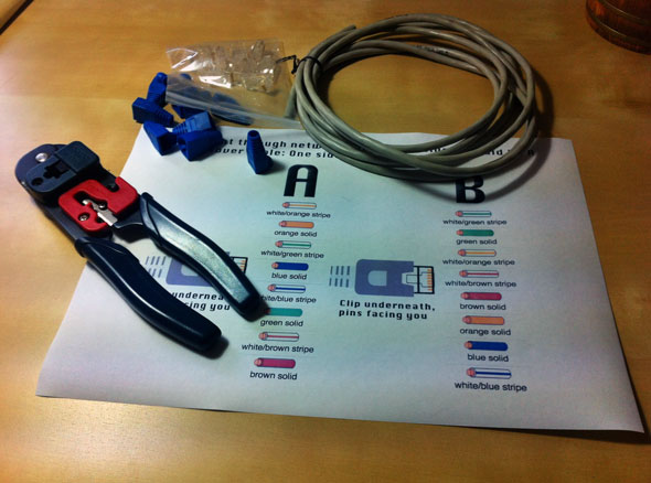
Tools and parts needed
- Ethernet cabling. CAT5e is certified for gigabit support, but CAT5 cabling works as well, just over shorter distances.
- A crimping tool. This is an all-in-one networking tool shaped to push down the pins in the plug and strip and cut the shielding off the cables.
- Two RJ45 plugs.
- Optional two plug shields.
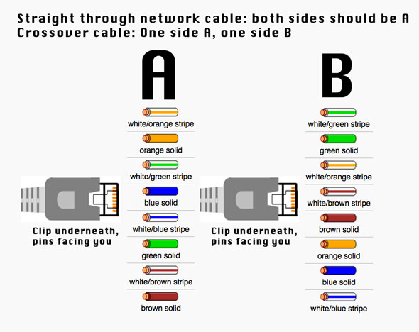
Crossover cable diagram
Additionally, you will need to either print out the diagram below or have it handy as a reference. Do note that sides A and B are not simply inverted.
How to make a crossover cable (step by step)
Step 1
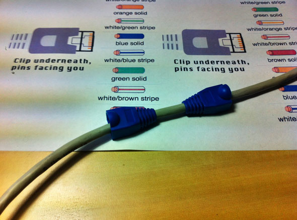
To start construction of the device, begin by threading shields onto the cable.
Step 2
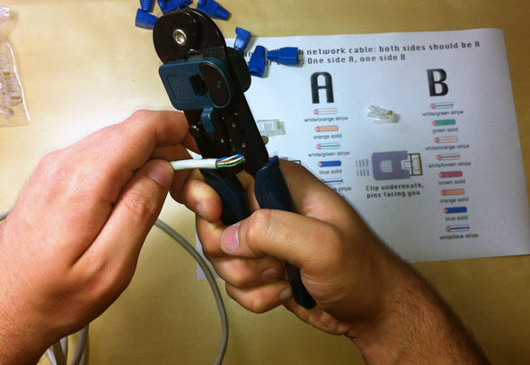
Next, strip approximately 1.5 cm of cable shielding from both ends. The crimping tool has a round area to complete this task.
Step 3
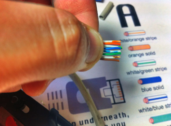
After, you will need to untangle the wires; there should be four “twisted pairs.” Referencing back to the sheet, arrange them from top to bottom. One end should be in arrangement A and the other in B.
Step 4
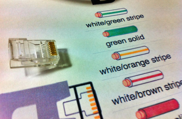
Once the order is correct, bunch them together in a line, and if there are any that stick out farther than others, snip them back to create an even level. The difficult aspect is placing these into the RJ45 plug without messing up the order. To do so, hold the plug with the clip side facing away from you and have the gold pins facing toward you, as shown.
Step 5
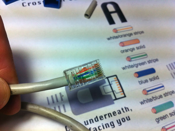
Next, push the cable right in. The notch at the end of the plug needs to be just over the cable shielding, and if it isn’t, that means that you stripped off too much shielding. Simply snip the cables back a little more.
Step 6
After the wires are securely sitting inside the plug, insert it into the crimping tool and push down. It should be shaped correctly, but pushing too hard can crack the fragile plastic plug.
Step 7
Lastly, repeat for the other end but using diagram B instead.
To test it, plug it in and attempt to connect two computers directly. While LEDs differ by the device, one should show activity and the other should indicate speed.
If you would rather buy a crossover cable, take a look at our selection.
Source: MakeUseOf
Related articles:
Advertisement
Learn more about Electronic Products Magazine


