BY KARL WALLINGER, Applications Engineer, Integrated Power Management, and ANKUR VERMA, Applications Engineer, Signal Chain
Texas Instruments
www.ti.com
Electric vehicles (EVs) use several kilowatts of energy to drive the ac synchronous propulsion motor from 400-V lithium-ion (Li-ion) batteries. The dc/dc circuits used to charge the batteries generate large amounts of EMI that can surpass stringent standards, such as IEC 61000-3-2 or IEC 61000-3-4 [1], so designers need to use an input filter with carefully selected components.
To help designers in this process, this article explains the system-level architecture of an EV onboard charger and why power factor correction (PFC) is needed. We then show how to design an input EMI filter that helps to meet radiation standards such as CISPR25, including calculations to select the filter components.
The application example covers a 50-Hz 220-Vac input ac offline power supply used for an automotive on-board charger in an EV. The same principles also can be applied when designing an industrial grid, power delivery systems, and motor position sensing systems [1, 3].
EMI sources
The on-board dc/dc circuitry used for battery charging typically uses pulse-width modulation (PWM) controllers that implement power factor control at switching frequencies that can vary anywhere between 50–100 kHz. The large voltages at such high-switching frequencies are the source of the electromagnetic radiation that sometimes can surpass IEC 61000-3-2 or IEC 61000-3-4.
These standards typically require admissible harmonic current components for emissions values to be within certain limits. Active PFC techniques, such as boost, help to mitigate electromagnetic compatibility (EMC). However, stringent applications may require additional electromagnetic interference (EMI) filters to pass the standard [2].
System overview: on-board charger for EV
The on-board charger for an electric vehicle deals with high power that can range from 1.5 kW to 3 kW, depending on the system. The universal input voltage of 90- to 265-Vac must be boosted up to 380–400 Vdc before the field-effect transistor (FET) full-bridge can chop it down to the lower dc voltage used to charge the batteries and run the system. Boosting is typically done with the PFC stage in order to increase efficiency and reduce losses (see “ Why is PFC important?”).
In these high-power ranges, the PFC stage is commonly interleaved to reduce the output ripple current and mitigate EMI emissions. The PFC boost output voltage of 380 to 400 Vdc typically supports currents above 10 A. An H-bridge circuit is used to chop it down in order to match the Li-ion battery’s charging profile (Fig. 1 ). The system also must support functional safety requirements and meet emissions standards. In addition, the designer needs to understand how power factor control is implemented and why it is critical in the system-design process.
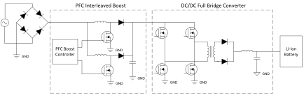 Fig. 1: System diagram of a typical automotive on-board charging solution. The PFC output of 380 to 400 V is chopped using an H-bridge to match the Li-ion battery’s charging profile.
PFC and its impact on EMI
Along with high dc/dc switching frequencies, other sources of EMI include higher ripple currents. These can lead to high dV/dt in the system, causing EMI emissions. Also, the boost’s output current is discontinuous and may lead to EMI emissions because of its high RMS currents; thus, it requires filtering by the output capacitor.
Power factor control can help reduce EMI with the help of a PWM controller that performs interleaving, as mentioned above (a good example for reference is the UCC28070-Q1). Interleaving’s introduction of multiple phases that are out of phase greatly reduces both input and output ripple.
Interleaving can be done in two or multiple phases. In a two-phase interleaved converter, for example, the input phases run at 180° out of phase from each other. Some PWM controllers for the PFC boost operation have phase-management capability that can help to manage compromises between the switching and conduction losses.
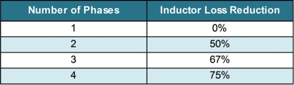
Also, current harmonics at the input of the power supply directly contribute to the EMI content. Each additional phase reduces the input ripple current; hence, the input EMI filter size can be reduced accordingly. Moreover, the phases reduce I2 R conduction losses in the inductor (Table 1 ).
Table 1: Inductor loss reduction for interleaved PFC phases. Each additional phase further reduces losses.
Now we will look at an example design to show how to tackle EMI in a 50-Hz, 220-Vac input ac offline power supply used for an automotive on-board charger used in an EV.
Tackling EMI with filter design
Different standards, such as the IEC61000-3-2 and IEC61000-3-4, provide limits for harmonic components of input current. These standards dictate a maximum level of each system fundamental frequency harmonic up to the 40th harmonic. Also, there may be radiated emissions requirements for the system, such as CISPR 25, which is dedicated to radio emissions limits for vehicles from 150 kHz to 2.5 GHz. To minimize EMI and harmonic distortion and to meet these requirements, an EMI filter should be placed at the input of the PFC boost converter. This example looks at input-filter design and component selection to reduce the harmonic emissions of the on-board charger using a PFC boost converter.
One example of an EMI filter is created using an inductor-capacitor (LC) filter. Two common options are second- and fourth-order LC filters. Although other filters can be used, our example looks at these. A second-order LC filter achieves attenuation of –40 dB per decade, while a fourth-order LC filter achieves attenuation of –80 dB per decade. For this reason, a second-order LC filter requires higher-value L and C components for the same level of attenuation, creating higher cost and a larger solution. Therefore, we will use a fourth-order LC filter in our example.
First, we need to run a design simulation or take actual board measurements of the design’s EMI levels. Let us assume that we ran a simulation and that a 50-dB reduction must be achieved at 150 kHz. Because a fourth-order LC filter has –80 dB/decade attenuation, we calculate the filter’s crossover frequency using Equation 1.
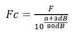
Equation 1.
Fc is the crossover frequency, F is the frequency at which you need to attenuate, and a is the amount of attenuation desired in dB. Applying the values from this example, F = 150 kHz and attenuation = 50 dB, Equation 2 shows the calculation and Equation 3 shows the result.
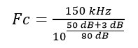
Equation 2.
Fc = 32.6 kHz
Equation 3.
Since this is a fourth-order LC filter, we will need two LC filters, each with a 32.6-kHz crossover frequency. Next, choose an L value based on size, current, and cost. For this example, we choose 470 µH. Now we can calculate the C value using Equation 4.
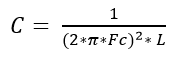
Equation 4.
C is the filter capacitance, Fc is the crossover frequency, and L is the filter inductance. Using the values from this example, Fc = 32.6 kHz and L = 470 µH, C can be calculated using Equations 5 and 6.
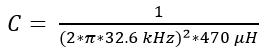
Equation 5.
C = 50.7 nF
Equation 6.
We chose a 75-nF capacitor to allow for dc bias and capacitor tolerance. This lets us build the filter circuit using two 470-µH inductors and two 75-nF capacitors.

Fig. 2: Fourth-order EMI filter with calculated component values for a 50-dB reduction in EMI at a frequency of 150 kHz.
Conclusion
When designing an ac offline power system like an automotive on-board charging module, implement a PFC controller to improve power factor and efficiency. When doing so, implement it as a multi-phased boost converter, to reduce the input ripple current and improve EMC performance.
To further improve EMI in order to meet harmonic emissions or radiated emissions requirements, use a fourth-order LC filter to attenuate emissions above the crossover frequency. By selecting the appropriate components, the EMI filter can sufficiently reduce emissions levels to meet the strict requirements of current industry standards.
References:
- Ankur Verma and Brian Rodriguez. “ Electrical design considerations for industrial resolver sensing applications.” Texas Instruments White Paper (slyy100), June 2016
- Ankur Verma. “ How to reduce total harmonic distortion to below 10%.” TI E2E Community Power House blog, May 28, 2013
- Verma, Ankur and Anand Chellamuthu. “ Design considerations for resolver-to-digital converters in electric vehicles.” Texas Instruments Analog Applications Journal, 1Q 2016
Advertisement
Learn more about Texas Instruments


