For those who enjoy building radio projects, you may have noticed that variable capacitors are not as available as they once were. There was a time when all radio receivers contained at least one, but with the arrival of the varicap diode and frequency synthesizer, the traditional tuning capacitor is difficult to find.

Fortunately, a variable capacitor is a simple device and one that you can easily construct yourself. You’ll need two machine nuts, one single-sided or double-sided PCB (½” x ½”), one machine screw, 12” of 22-gauge magnet wire that is enamel-coated, one hacksaw blade, and a piece of plastic.
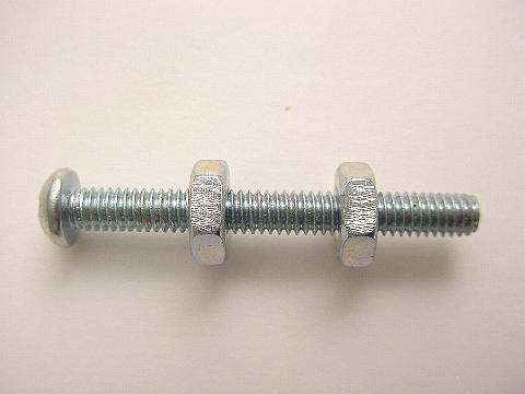
Start by screwing the two nuts onto the screw itself. Each hex nut needs to be scratched with a one-sided razor blade, but only on one side. The scratching ensures the soldering adheres to the nut.

Once you’ve scratched up your two nuts, place a generous dab of solder onto each side (enough to cover the entire side) of each nut. Be sure to hold the soldering gun onto the nut for a good 30 seconds, ensuring that the solder adheres well to each nut. You should see the solder begin to grab onto the nut after several seconds.
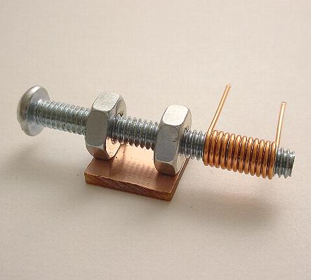
After you have a firm dab of solder on each side of each nut, take your PCB and place it under the two nuts. Adjust the two nuts so each rests on each side of the PCB. Once this is done, there will be an approximate ¼” between the two nuts.
Next, place some heavy form over your setup, ensuring it does not move. Take your soldering gun and heat up the solder on one of the nuts. When it becomes soft, start applying more solder to that area. Once the solder has accumulated enough, the weight of itself will fall directly onto the PCB. When the one adheres to the PCB, do the same for the other nut.
Now grab your 12” of 22-gauge wire and unscrew your screw from the two nuts. Make 12 wraps of wire around your screw. After you’ve made 12 turns, cut the excess off, leaving ½” of wire on the ends. Go ahead and unscrew your “coil” from the screw.

Measure 16 mm up from the bottom of the head of the screw. Take a new single nut and position it where the 16 mm is, and using your hacksaw blade, cut at that point. The new nut is placed to keep an accurate measurement while you cut. Once you’ve finished making your cut, take the screw and screw it into your two soldered nuts that are now attached to the PCB. Turn the screw all the way and take your newly-made coil and screw that onto your freshly-cut screw.
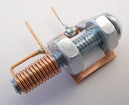
The final step involves putting a piece of folded plastic underneath the screw between the two nuts. If you don’t put the plastic underneath, there will be no tension on the screw. Thus, when you turn it, you will get sporadic discontinuity between the screw and the nuts. The plastic gives an upward push on the screw and the two nuts, providing a continual continuity between the two.
Lastly, bend the outside end of the coil wire toward the inside end wire and snip off the excess. Taking your single-edged razor blade, scrape off the enamel-coated insulation where the two wires come together, and solder them in place.

Take a small piece of the 22-gauge wire and scrape off all of the enamel. Solder one end to the PCB in between the two nuts. Snip off the end, so both terminals are equal, making it around ½”. You’ll now have your two terminals that can be soldered into place on whichever RF project you’re working on.
The wire soldered to the PCB acts as a rotor, which is the turntable portion of the device, while the wire coming from the coil acts as the stator. If one of your terminals on your project is ground, always connect the “rotor” end wire to the ground, as it will eliminate the capacitance when your hand turns the screw for adjustment.
Source: Earthground
Advertisement
Learn more about Electronic Products Magazine


