By Bonnie Baker and Martin D. Stoehr, Maxim Integrated
We live our lives in a wireless world, from our short-range radio toys to our garage door openers, which become our own personal internet of things encircling our entire home. These radio tools and toys connect our lives through short-range wireless transmitters and receivers. Each of these applications presents challenges for radio designers to overcome, from maximizing connection distances to grappling with the Wi-Fi or Bluetooth regulatory jungle (Fig. 1 ).

Fig. 1: A wireless home or building system becomes a radio jungle when communicating with all functions.
This article focuses on the SRD transmission block by providing useful environmental transmission insights and techniques to increase transmission power, along with tips to reduce supply current.
UHF sub-GHz SRD networks
Short-range radio devices can be unidirectional or bidirectional radio transmitters. The frequency band of SRD transmitters and receivers are commonly in the sub-GHz range, below those for competing wireless regulated technologies, such as Wi-Fi (900 MHz, 2.4 GHz, 5.9 GHz, and others) and Bluetooth (2.4 GHz to 2.4835 GHz).
The term SRD applies to low-power, sub-GHz radio devices designed to operate across reasonable distances of 100 m. A simple SRD system, such as a garage door opener, consists of a transmit-to-receive single channel with intelligence and power supplies on both sides (Fig. 2 ).
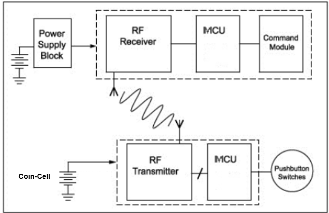
Fig. 2: An SRD block diagram contains an RF transmitter and receiver.
In Fig. 2 , the communication between the transmitter and the receiver carries information from a simple button or switch. The bottom portion of Fig. 2 shows an SRD transmitter block that has a radio frequency (RF) transmitter, microcontroller, pushbuttons or switches, and a coin-cell battery. The top portion of Fig. 2 shows the SRD’s receiver block that has an RF receiver, microcontroller with a command module, and a power-supply block.
In the system shown in Fig. 2 , the transmitter block (bottom portion) is battery-powered, requiring low-power components to support the longevity of the coin-cell battery, while still allowing the RF transmitter to send a signal strong enough to maintain a link over the required distance.
SRD communication link
The SRD transmission channel resides at the ground level, as opposed to long-range, open-space transmissions. Consequently, there are two signal paths to consider in a typical SRD transmission (Fig. 3 ).
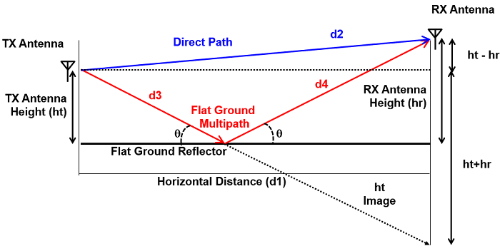
Fig. 3: Flat-ground multi-path graphic transmission dynamics.
In Fig. 3 , the transmitter sends the signal to the receiver starting from the transmitter antenna (TX). The primary path to the receiver antenna (RX) is the direct path along which the signal travels a distance equal to d2 (blue line) or R.
Equations 1 and 2, the Friis calculation, assist in determining the direct-path transmission margin.
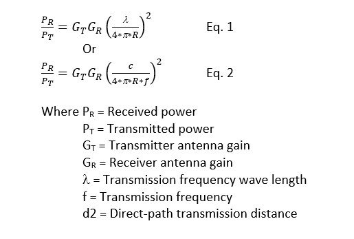
Equation 1 calculates the signal transmission power. Notice that the power at the receiver drops by a factor of 1/d22 .
Using a 434-MHz signal over a 100-m transmission path, the transmitter-to-receiver path attenuation is –62 dB.
A secondary signal path is generated through the flat-ground multi-path or ground-reflected route. This distance is equal to d3 + d4 and, in addition to the small change in phase from the extra distance, the ground reflection causes a 180° phase reversal. Losses from the multi-path signal further degrade the overall transmission power of the signal seen by the receiver.
The link budget spreadsheet (download)highlighted in the application note “Radio Link-Budget Calculations for ISM-RF Products ” provides a reliable calculation of this multi-path signal loss.
Transmission losses
Improvements in the SRD communication range can be realized by making changes to the transmitter and receiver as well as making refinements to the antenna design. Signal attenuation occurs through faulty hardware connections, ill-designed antennas, a direct-path channel, or obstructions from physical structures. Fig. 4 illustrates a complete 433.92-MHz link budget for a 100-m transmission channel.
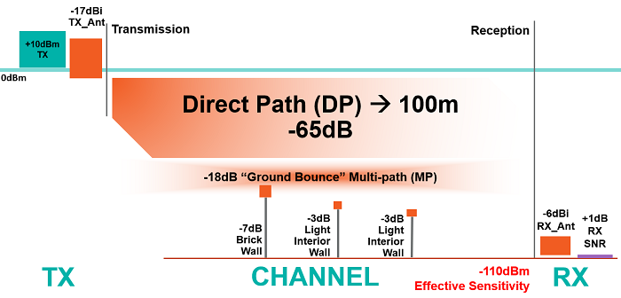
Fig. 4. Typical SRD 433.92-MHz link budget at 100 m, providing –110 dBm effective sensitivity.
In Fig. 4 , the industrial, scientific, and medical radio band (ISM) signal power for a 434-MHz frequency transmission over a 100-m distance of a home SRD application has a direct-path attenuation of –65 dB. The RF environmental SRD variables included in a link budget calculation are transmitter power (TX), transmitter antenna gain (TX_Ant), direct-path attenuation (DP), multi-path attenuation (MP), attenuation from obstructions (OB), receiver antenna gain (RX_Ant), and the receiver margin (RX_SNR).
Starting with the transmitter in Fig. 4 , the transmitter’s power amplifier has an output of 10 dBm. The signal then travels through an antenna (TX_Ant) that causes a signal attenuation of –17 dBi. The signal travels across the channel with two routes, the direct-path (DP) signal that accounts for 65 dB of attenuation and the multi-path (MP) route, which causes an additional 18 dB of attenuation. Physical obstructions take another 13 dB of power from the signal. Upon arrival at the receiver block, the RX antenna (RX_Ant) causes a 6-dB loss, which results in a total received signal strength of –109 dBm.
When using a receiver with a specified sensitivity level of –110 dBm, this system configuration provides only 1 dB of margin (RX_SNR) when attempting to decode the transmitted signal. In this example, the TX_Ant and RX_Ant values include connection filtering, losses, and impedance-matching errors.
The received signal strength (RSS) can be calculated by subtracting the loss due to each element from the original transmitted power (Equation 3).
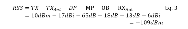
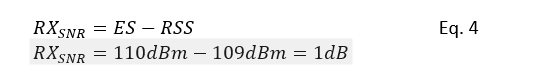
The difference between the calculated RSS and the effective sensitivity of the receiver is the margin, or RX_SNR.
The often-overlooked variables in this calculation are the flat-ground multi-path and physical obstructions such as brick walls and interior walls. In the previous discussion, there is accommodation for both the flat-ground multi-path and physical obstructions. Looking at Fig. 4 , what remains of the transmitted signal is a very small amount of RSS, which is prone to noise interference.
From a theoretical perspective, the link budget spreadsheet and its related application note, “Radio Link-Budget Calculations for ISM-RF Products ,” are good starting points for learning about and calculating the SRD channel evaluation. As a radio system designer will find, this SRD system budget calculator helps determine several useful trade-offs such as receiver sensitivity versus estimated range.
Tricks of the trade
Enhancements to the wireless range offered by this system are possible with a higher power transmitter (TX) output, better antennas (TX_Ant, RX_Ant), and better receiver (RX) sensitivity.
Higher power transmitter: Higher power transmitters can effectively translate into more decibels at the receiver. Commonly, this increase in TX power translates into a requirement for more current from the transmitter power supply or battery. In turn, the increased current shortens the battery life or increases the remote package size with a larger battery. The MAX41460-MAX41464 family of transmitters, as examples, can provide an additional 6 dB of output power over conventional transmitters without compromising the device’s power-supply requirements.
The MAX4146x family of devices includes high-output-power, low-current transmitters with up to 16 dBm of transmitted power that run on a 3-V coin-cell battery. This is achieved while keeping the supply current below 12 mA in ASK modulation (434 MHz, 3.0 V) and below 12 mA for FSK modulation (434 MHz, 3.0 V), which has little to no impact on the power budget. The devices provide over 16-dBm output power with a high power match or by using “boost mode” with current typically below 45 mA.
These transmitters allow more than 30 m of extra range without any penalty for battery-powered systems. By using optimized high power matching and/or boost-mode operation, as much as 60 m of additional range can be realized.
Better antennas: A better antenna design typically involves a larger antenna size. Common SRD operating frequencies are 315 MHz, 434 MHz, or 868 MHz/915 MHz. For these frequencies, the ideal length of the antenna should be a ¼-wavelength antenna equating to 23.8 cm, 17.9 cm, or 8.6 cm/8.2 cm, inclusive. For small-form-factor, battery-powered transmitters, none of these lengths are visually appealing or practical, so the design ends up with a transmitter antenna that is smaller than ideal yet “good enough.”
On the receiver side, it is possible to find room for the larger antenna size. Again, for an omnidirectional, ¼-wavelength monopole antenna (PCB trace loop or bent-monopole), there is potential for signal gain rather than attenuation. Changes to the receiver antenna can improve the signal power in Fig. 4 from –6 dbi to 1 dBi or more.
Better RX sensitivity: Improvements to receiver sensitivity act as a direct improvement to the SNR or link margin of the system. A change in the RX sensitivity from –110 dBm to –115 dBm directly provides an additional 5 dB of SNR. The trade-off for this improved sensitivity typically comes at the expense of increased power-supply current. More sensitive SRD receivers usually impact the cost of the solution as well.
Overall, the sweet spot to increase the SRD system range hinges on design time, bill of material (BOM) cost, and power budgets. These considerations point to utilizing a higher-output power transmitter.
Fig. 5 shows an improved 433.92-MHz SRD system with better link margin (SNR) obtained by implementing all of these suggested improvements.
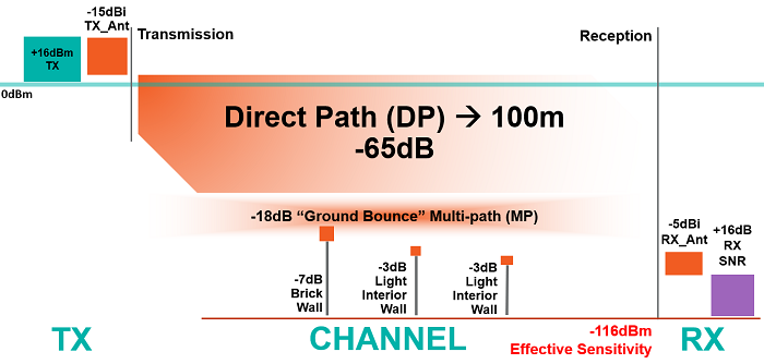
Fig. 5. Typical SRD 433.92-MHz link budget at 100 m provides a –116-dBm effective sensitivity.
The difference betweenFig. 4 and Fig. 5 is the use of a 16-dBm versus a 10-dBm transmitter, which not only provides an improvement in TX_Ant attenuation from –17 dBi to –15 dBi but an improvement in RX_Ant from –6 dBi to –5 dBi and an improved receiver sensitivity from –110 dBm to –116 dBm. All of these improvements increase the SNR from 1 dB to 16 dB.
Conclusion
SRDs appear in a large variety of applications that need short-distance and low-power data transmission channels. In many instances, existing standards such as Wi-Fi or Zigbee are not appropriate primarily because of supply current requirements. These design constraints open the way for the use of SRDs. This article showed how to maximize transmission ranges using a high-gain, low-power RF transmitter.
Learn more:
MAX41460 300MHz–960MHz ASK and (G)FSK Transmitter with SPI Interface
MAX41461 300MHz–960MHz ASK Transmitter with I2 C Interface
MAX41462 300MHz–960MHz ASK Transmitter with I2 C Interface
MAX41463 300MHz–960MHz (G)FSK Transmitter with I2C Interface
MAX41464 300MHz–960MHz (G)FSK Transmitter with I2 C Interface
About the authors:
Bonnie Baker is an electrical engineer who has written three analog design books, starting with “A Baker’s Dozen: Real Analog Solutions for Digital Engineering” (2005). In past roles, Burr-Brown, Microchip, Texas Instruments, and Maxim Integrated facilitated her involvement in analog design and analog systems for the last 30+ years. Bonnie holds a master’s degree in electrical engineering from the University of Arizona (Tucson, Arizona) and a bachelor’s degree in music education from Northern Arizona University (Flagstaff, Arizona). In addition to her analog design fascination, Bonnie has a drive to share her knowledge and experience through the authorship of over 500 articles, design notes, and application notes.
Martin D. Stoehr has been working in the analog and mixed-signal IC industry since graduating from the University of Colorado in 1994 with a BSEE in communication systems and control theory. For the past 18 years, he has been designing various board-level systems at Maxim Integrated, from fully automated bench test systems to characterization boards, evaluation kits, reference designs, and demonstrators. He is currently the manager, applications engineering, at Maxim Integrated. In 2014, Martin was awarded “Article of the Year” for 2013 from Elektronik Magazine for his article “Kurzstrecken-Funksysteme professionell entwickeln” (“Getting Started with a Radio Design”)[1]
1. Elektronik Magazine article “Kurzstrecken-Funksysteme professionell entwickeln” (English title: “Getting Started with a Radio Design”), “Article of the Year” for 2013, http://www.elektroniknet.de/elektronik/halbleiter/die-elektronik-autoren-des-jahres-2013-107374-Seite-4.html
Advertisement
Learn more about Electronic Products MagazineMaxim Integrated


