BY DAVID McPARLAND
Senior Product Manager, Oscillator Products
Silicon Labs
www.silabs.com
Crystal oscillators are often one of the last components that a designer thinks about, but the wrong part can quickly kill a design. Moreover, searching through a wide variety of available oscillators and their capabilities can be confusing. There are four key questions you should ask yourself when selecting an oscillator. The answers you find will help to ensure that your design’s requirements are met.
Do you need a crystal or an oscillator?
While they may look identical and share many specs, crystals and oscillators are very different devices. A packaged crystal is a piece of quartz, cut and polished to resonate at a specific frequency with a high Q-value. It does not contain the oscillator circuit that drives the quartz to produce a clock output. Instead, the drive circuitry resides inside the device to which the crystal is connected.
In contrast, a crystal oscillator, or XO, is a complete device that contains the quartz crystal, oscillator circuit, output driver, and potentially a phase-locked loop (PLL). An XO provides a clock output at a specified frequency and signal format, such as CMOS, LVDS, and LVPECL. An oscillator (Fig. 1 ) can either drive a chip directly or be fed through a buffer to provide multiple copies of a particular frequency. 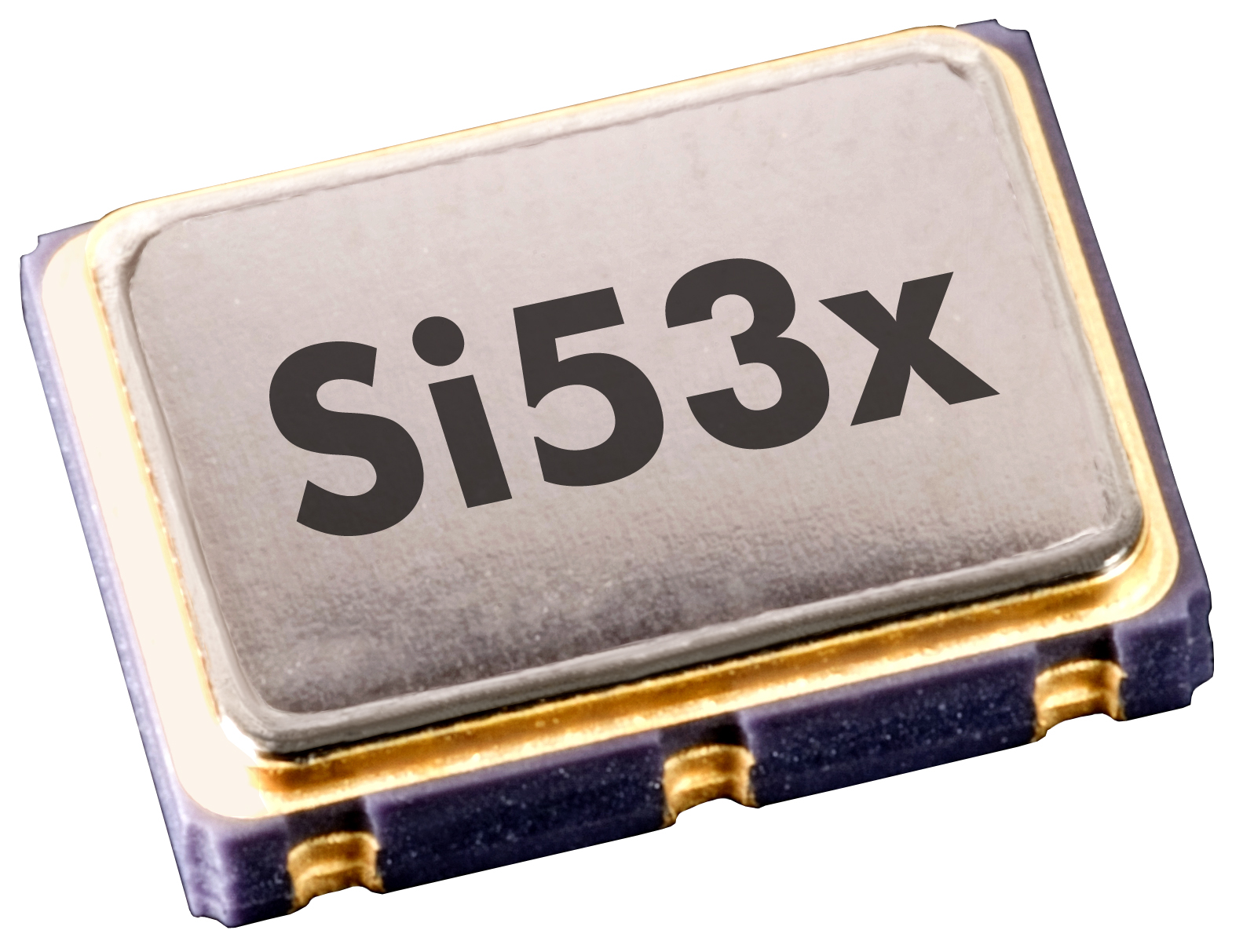 Fig. 1: An oscillator is a complete, single-output clock generator.
Most consumer and battery-powered applications use system-on-chip (SoC) devices with integrated oscillator circuitry and a simple, low-cost crystal for clock synthesis. For higher-end applications — data center, telecom, industrial automation, etc. — an external XO is typically used to provide reference timing for the SoC’s internal PLLs.
Using an off-chip clock source is advantageous because it offers an independent, isolated reference clock optimized to provide low-jitter operation with minimal crosstalk. Another notable benefit is that oscillators incorporate integrated power supply noise rejection to minimize the impact of board-level noise on clock jitter.
What jitter performance is required?
Timing jitter is a way of measuring the purity of a clock signal. The lower the jitter, the less noisy it is. Since the oscillator typically functions as the local “heartbeat” of the system, a clean and low-jitter output is desirable.
Jitter is measured in either the time domain on an oscilloscope — for example, period jitter and cycle-to-cycle jitter — or in the frequency domain on a phase-noise analyzer with RMS phase jitter integrated over a frequency band, such as 12 kHz to 20 MHz, as shown in Fig. 2 . 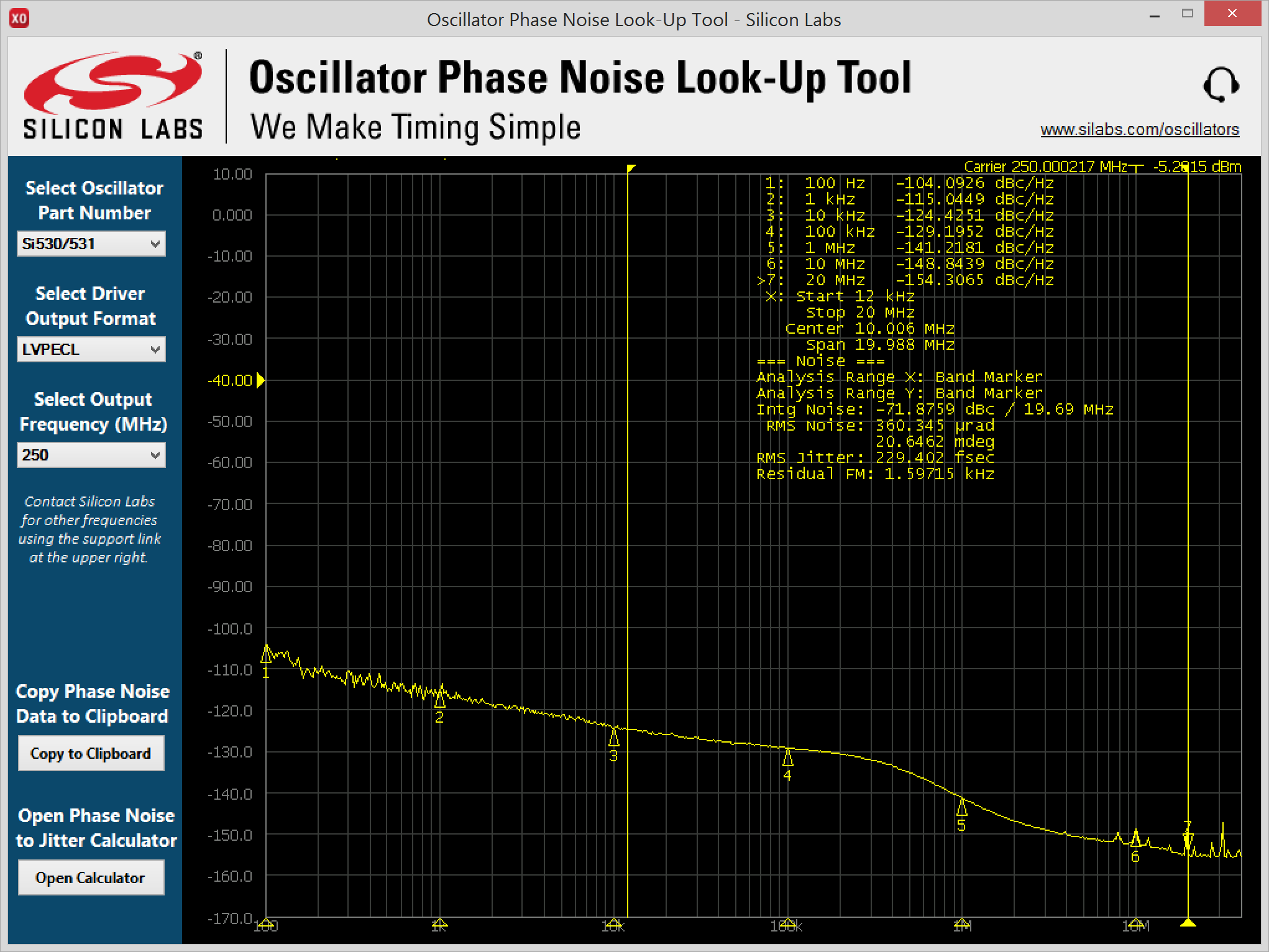 Fig. 2: XO phase-noise lookup tool.
Low-phase-jitter XOs with
Will your frequency change?
Many oscillator applications only require a single, fixed frequency like 156.25 MHz. In other cases, the frequency provided by the oscillator may need to change. For example, a 12G-SDI video framer may need to toggle between two different video frame rates of 297 MHz and 297/1.001 MHz.
At other times, it may be desirable to intentionally add a small frequency deviation as part of margin testing to stress-test the system-level setup and hold times. Perhaps most commonly, designers may not yet know exactly which frequency the final design will use, but they know that they will need an oscillator to provide this reference.
For such applications, the ideal solution is an oscillator that provides multiple, pre-stored frequencies. Dual and quad oscillators are available for these applications. The output frequency of these devices is pin-selectable, enabling a single XO to replace multiple oscillators and a mux. If the application requires a mix of integer and fractional clocks, select a device that offers consistently low-jitter operation across all target frequencies.
Another useful type of oscillator is an I2 C-programmable XO. These devices offer the most frequency flexibility, providing consistent low-jitter operation over a wide frequency range. These devices can be reprogrammed on the fly to provide a nearly infinite number of frequencies.
They are also very useful for prototyping and use in digital PLL architectures, in which a host processor provides a fast digital-feedback mechanism to allow the XO to lock to and track a reference signal.
How important is frequency stability?
Frequency stability is a measure of how much the oscillator’s output frequency potentially changes during operation due to a change in temperature. If the frequency drifts beyond what the application expects, timing errors are likely to occur. Frequency stability is expressed in parts per million, or ppm, relative to a nominal frequency over a specific temperature range.
Oscillators use quartz crystals cut at different angles during manufacturing to produce different temperature responses. Common XO temperature-stability ratings include ±20 ppm, ±50 ppm, and ±100 ppm. A lower ppm means that the output frequency is more stable over the given temperature range.
It’s worth noting that frequency stability is only one aspect of knowing how much an oscillator’s frequency may change. A complete measurement of potential frequency deviation is called total stability, which is the sum of frequency stability over temperature, initial accuracy at 25°C, and aging over a specified time and temperature. Total stability, as shown in Fig. 3 , reveals the worst-case-possible frequency that the oscillator might produce over its operating life. 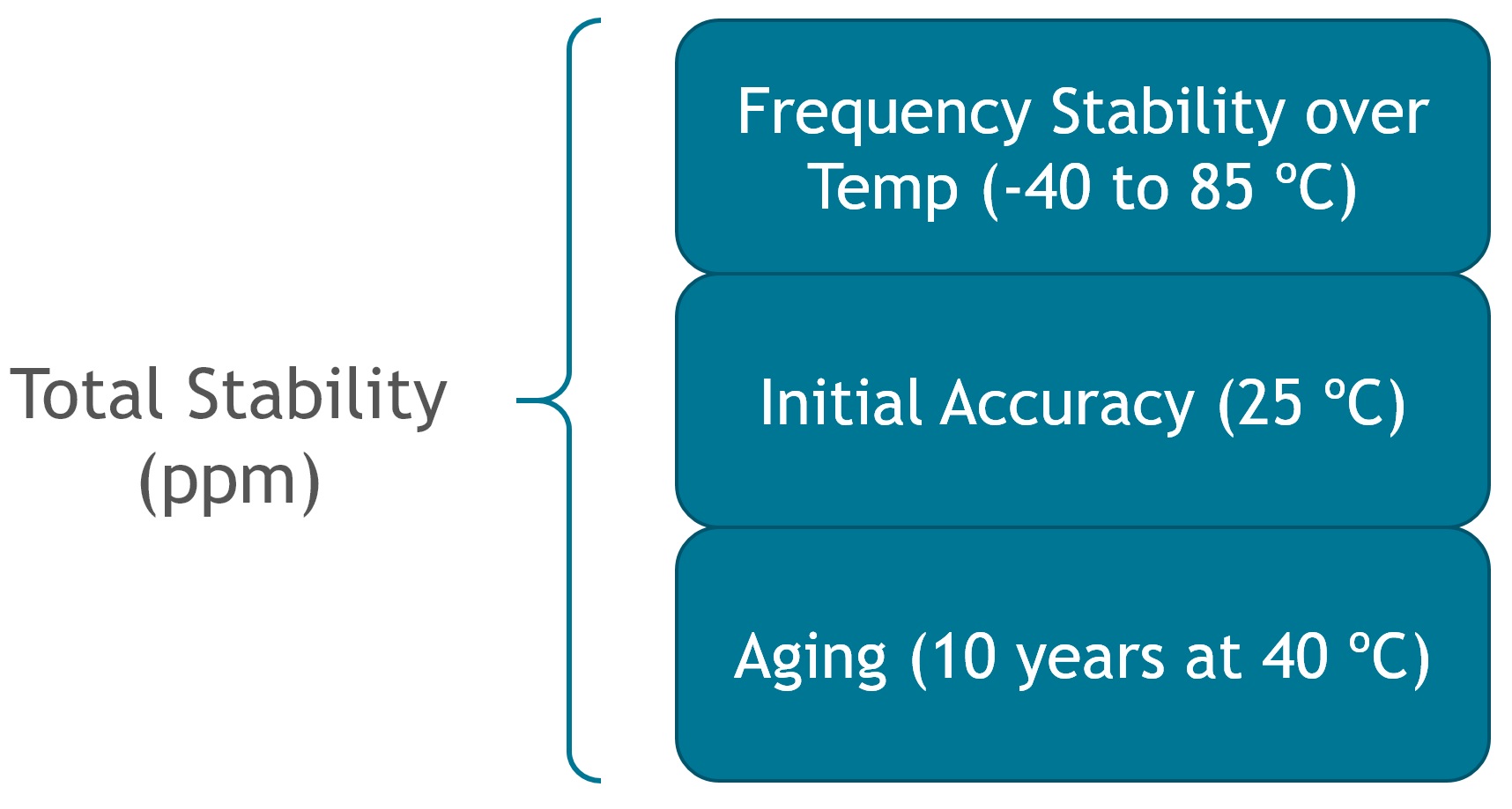 Fig. 3: Components of total stability.
An XO may have excellent frequency stability over temperature, but this measurement is only relative to the nominal frequency that it provides at room temperature. So initial accuracy error can be quite large for some devices, such as SAW oscillators, and must be taken into consideration.
Similarly, quartz crystals slowly age over long periods of time, which causes the output frequency to drift slowly. Some oscillator suppliers specify aging for only one year at 25°C, while more conservative suppliers specify aging for 10 years at higher temperatures, providing a more reliable guarantee for long-term operation.
The aging condition can make a substantial difference in the total stability of the oscillator and can sometimes make an apples-to-apples comparison difficult. When in doubt, it is safer to use a timing device with guaranteed specifications over more stringent conditions to provide more design margin.
Advertisement
Learn more about Silicon Labs


