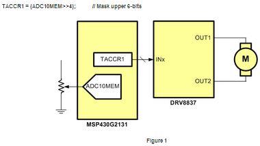
In motor applications, it’s suitable to respond to a varying input command with a nonlinear output response to allow compensation for a machine limitation and to provide a better user experience. For example, in an application with an analog input speed command from a potentiometer, it is common to scale the measured input with an analog-to-digital convertor (ADC) and write the value directly to a pulse width modulated (PWM) output unit that drives an electric motor. This provides and 1-to-1 linear input-to-output response.
With a linear response and the potentiometer at 0% input, the PWM output is 0x00, at 25% 0x0F, full on 0x3F assuming a system with 6-bits of resolution. An embedded system block diagram that measures a potentiometer input with a 10-bit ADC (ADC10MEM) directly writes to a PWM output (TACCR1) controlling a DRV8837 which ultimately drives a brushed DC. This is shown below Figure 1. The required line of firmware that directly moves the measured 10-bit ADC10MEM as a 6-bit PWM value is also shown below.

If the application is a throttle speed input on an electric bicycle, consider providing a nonlinear response with a more exponential transfer function applied to the motor drive. For a given speed input change, the output initially responds with a smaller PWM increase and the larger PWM increases near full scale, enabling greater control at lower speeds and more response at higher speeds.
This type of nonlinear response uses a simple speed look-up table. With 6-bits of resolution, this equates to a table with 64 entries. The firmware and un-utilized speed table are shown below.
cont char SpeedStep[64]; // SpeedStep table
PWMRXD = SpeedStep[ADC10MEM>>4]; // PWM from 64-step array
There are two primary system advantages to using a speed look-up table for a nonlinear input to output response – simplicity and flexibility.
The simplicity is seen in the firmware that requires only the addition of the look-up table and indirect memory access, both highly transparent using C-code. The look-up table is simple to code and efficient from a processing perspective. Modeling nonlinearity mathematically often requires many multiplications, divisions and even floating point which are computationally taxing on 8/16-bit MCU’s used in cost sensitive embedded systems.
Flexibility is realized in that within the same system, multiple look-up tables may reside for different profiles or a custom profile is built by the user. In an embedded system the speed-table, or tables, resides within an MCU’s nonvolatile FLASH memory, which is updated in-system as needed.
The examples describe a system with 6-bits of input and output resolution. But it is important to mention that both the input and output resolution can be scaled as needed to meet the needs of the overall system goals. They do not need to be identical.
Using a simple speed table allows the designer to more easily build a unique system response with low complexity and very little, if any, cost.
See more factory automation solutions
Advertisement
Learn more about Texas Instruments


