How selecting the right capacitor can increase the lifetime of your LED lighting design
BY NAOYUKI KOBAYASHI
Senior Product Manager
Murata Electronics
www.murata.com
With a new focus on green technology and eco-friendly products, American households and companies are now familiar with light-emitting diodes (LEDs). The market for these products is extensive; practically any traditional method of lighting can be replaced with an LED.
With their ability to provide efficiency and longevity, LEDs represent the cutting edge of new energy technology, but a simple misstep in the design can cause their life to end prematurely. As this market is still evolving, many engineers do not realize that the wrong capacitor in the LED circuit can cause the light to fail long before the expected lifetime. That is because some capacitors, when subjected to very high voltages, will stop working. For that reason, it is crucial to choose the right capacitor.
Components for LED lighting design must be selected carefully to ensure that they meet the lifetime and energy-efficiency requirements of the end products. These requirements can be demanding LED lighting products may have an expected lifetime of more than 40,000 hours. Therefore it is critical that all parts of the circuit can meet these requirements.
Ceramic capacitors in this type of circuit can be subject to high voltages and conditions unlike those usually seen in other domestic appliance applications. These conditions can adversely affect the lifetime of ceramic capacitors, which can mean they fail before their expected minimum lifetime. This article explains the root of this problem and makes recommendations for ensuring ceramic capacitors do not shorten the lifetime of LED lighting products.
Typical conditions in LED circuitry
A typical LED lighting circuit is shown in Fig. 1 . The capacitors selected for C1 , C2 , and C3 should be safety-recognized devices rated to 250 Vac. C6 is the snubber capacitor for the diode; parts rated to withstand 250 to 630 Vdc are needed and these can have the X7R temperature characteristic. For C7 , the snubber capacitor of the field-effect transistor (FET), a higher voltage rating of 630 Vdc to 1 kVdc is necessary, and it is recommended that the U2J temperature compensated capacitor be used. C8 is the smoothing capacitor for the secondary circuit for which any 100-V-rated part should be sufficient.
The capacitors in the circuit subject to the harshest conditions are C4 and C5 , which act as ac smoothing or noise filter capacitors for the primary circuit. The typical working voltage signal across these two capacitors is the full-wave-rectified waveform shown in Fig. 2 . Capacitors with a X7R TC that are rated up to 250 Vdc are often incorrectly chosen for C4 and C5 . The problem is that when high-dielectric-constant capacitors like these are subjected to full-wave-rectified voltages, they succumb to the electrostrictive effect, which can cause fatal cracks in the dielectric material.
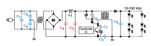
Fig. 1: A typical LED lighting circuit.
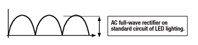
Fig. 2: Typical voltage waveform across C4 and C5 .
The electrostrictive effect applies to all EIA Class II dielectric materials (these are ceramics with a high TC or with a high content of barium titanate (BaTiO3 ). When an ac voltage is applied, the capacitor effectively stretches and shrinks in the different dimensions, as shown in Fig. 3 . Mechanical distortion and stress concentrate around the edge of the external electrode of the capacitor. If the ac voltage is large, and the material has sufficient dielectric properties, cracks can form under the external electrode over time, which can lead to catastrophic short-circuit failure of the component.
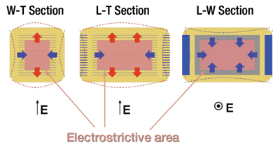
Fig. 3: The electrostrictive effect.
Mitigating the electrostrictive effect
There are a number of ways in which the electrostrictive effect can be mitigated with the use of specially designed capacitor structures.
The first factor to take into account is the thickness of the dielectric material between the inner electrodes of the capacitor. This has a direct effect on the magnitude of the electrostrictive phenomenon. When designing high-voltage capacitors, it is essential to ensure the dielectric layer is thick enough to reduce the chip capacitor’s internal mechanical stresses.
Secondly, the structure of the inner electrodes can contribute to the electrostrictive effect. Typical inner electrode structure is shown in Fig. 4a. By comparison, Fig. 4b shows one type of electrode structure of high-voltage capacitors. The center area of this structure (marked red in the figure) is not active and is therefore free from the effects of this phenomenon. This is sometimes referred to in the component industry as floating electrode structure.
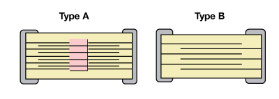
Fig. 4: Inner electrode structure.
Additionally, the thickness of the outer layer of the dielectric (the “dummy” layer) can influence the formation of cracks. This layer is where cracks usually begin, so increasing its thickness, and thereby its mechanical strength, can help reduce the chance of cracks forming and increase the lifetime of these products.
Lastly, the properties of the dielectric material itself can play an important part, since it is only high-dielectric-constant materials that experience the electrostrictive effect. Companies such as Murata carefully consider the properties of its materials to ensure that products specified for high voltage are constructed from suitable dielectric materials.
To address the reliability issues effecting C4 and C5 and increase the lifetime of the capacitors in C4 and C5 , Murata recommends using either of the following options insurface-mount and leaded construction. As mentioned previously, these recommendations are based on effects of the high-voltage, full-wave-rectified wave (greater than 250 V) to which the C4 and C5 capacitors are exposed.
Based on the voltage requirements of the plans, Murata recommends choosing capacitors with a 630-Vdc rating for designs having ac voltage ratings of 100 to 240 Vac. Due to the effects of electrostriction, it is recommended that for designs where the peak-to-peak voltage (Vp-p) is more than 50 V, a 630-Vdc part be used. For plans where the peak-to-peak voltage is less than 50 V, a 250-Vdc option can be considered. Cases sizes for ceramic capacitors parts that meet these conditions are generally 1210, 1812, and 2220.
For designs with an ac voltage of 277 V, it is suggested that the design use a 1-kV option. Case sizes for ceramic parts with the 1-kV rating can range from 1812 to 2220. The capacitance values that are generally needed for C4 and C5 are 0.047, 0.1, 0.22, 0.47, and 1 µF. There are a wide range of solutions in both SMT and through-hole technologies to best suit the design constraints of your design.
Overall, the conditions experienced by ceramic capacitors in LED lighting circuits should not be underestimated. It is Murata’s experience that selecting the wrong capacitor can adversely affect the lifetime of the end product due to crack formation in the dielectric material of these capacitors. When developing this type of product, engineers should take care to ensure they use adequately rated chip ceramic capacitors, with superior structure to mitigate the electrostrictive effect described above. ■
Advertisement
Learn more about Murata Electronics North America


