BY SUBBARAO LANKA, Senior Staff Applications Engineer,
and SHRUTI HANUMANTHAIAH, Staff Applications Engineer
Cypress Semiconductor
www.cypress.com
Liquid-level sensing is used in consumer electronics appliances like washing machines to detect the detergent level. The sensor technology has progressed to such an extent that refrigerators can now detect milk levels and notify users to buy more by messaging their cell phone.
There are two forms of liquid-level sensing: point-level sensing and continuous-level sensing. With point-level sensing, sensors are placed at discrete levels on the tank that holds the liquid to be measured. These sensors can be used to detect a full tank, an empty tank, and discrete liquid levels for lower resolutions, such as ¼ full, ½ full and ¾ full.
Take the case of an espresso machine with two reservoirs. The main reservoir is for the water used to produce coffee, while the other reservoir is a drip tray used to catch wasted water. A cappuccino machine will have a third reservoir for milk. Here, system operation needs to be interrupted when water levels in the main reservoir are below a predefined level to prevent the machine from burning itself.
System operation also needs to be stopped when the level in the drip tray has reached the maximum level allowed for its safe removal by the user. The machine needs to know whether the water supply is empty and the drip tray is full, and that’s where point-level sensing comes into play.
Next, continuous-level sensing allows the liquid level to be measured to a greater level of resolution. It’s particularly useful in systems like automobiles. For instance, many vehicles have started to measure diesel exhaust fluids that are mostly used in trucks and other diesel vehicles to help reduce emissions.
The fluid is sprayed into the exhaust of diesel vehicles — after the diesel has been combusted — to help convert oxides of nitrogen into harmless gas and water vapor. Diesel Exhaust Fluids (DEFs), which are likely to become a standard requirement in all diesel vehicles in the future, are stored in a separate tank from the fuel tank, away from the engine.
Traditional sensing techniques
Liquid-level sensing techniques can be broadly classified into mechanical- and microcontroller-based approaches. In mechanical-based sensing environments, a magnet is mounted on a float that moves at the level of liquid as it changes in the tank.
The float actuates a reed switch to control the system — it allows the flow of liquid or stops the flow of liquid. The mechanical floats offer high repeatability. However, because they have moving parts, they wear out over time.
The microcontroller-based sensors have largely been replacing the sensors using techniques like mechanical floating due to their lower accuracy, reliability, and operating life. First, there is conductivity sensing, in which two conductive electrodes are employed to measure conductivity. It’s a reliable method as compared to the mechanical-centric sensing method, but it cannot be used for beverages and flammable liquids.
The second MCU-based technique allows the level of liquid in a container to be measured using a pressure sensor. The sensor is placed at the top of the tank and is connected to a tube that is inside the tank. The amount of fluid in the tank exerts a proportional amount of pressure on the sensor via the compressed air in the tube.
The sensor produces a pressure-equivalent voltage, which can be converted to a digital signal for processing and evaluation. This method is suitable for low viscous liquids. However, it strongly depends on the atmospheric pressure and can be used only in non-pressurized tank applications.
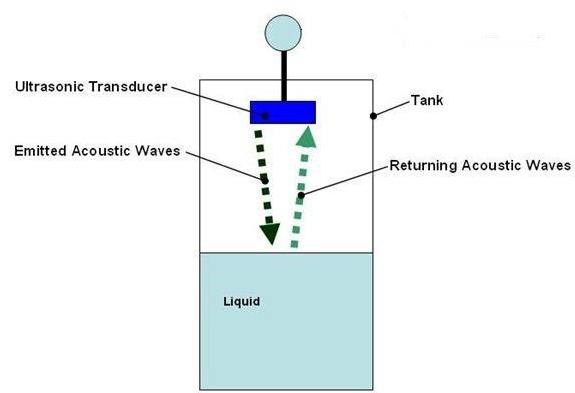
Fig. 1: Ultrasonic liquid-level sensor.
The third popular approach is ultrasonic sensing, in which ultrasonic transmitters and receivers are mounted on top of the tank pointed toward the liquid. The MCU transmits ultrasonic pulses to the liquid’s surface and observes the echo signal. The delay between the actual signal and the echoed signal indicates the presence or absence of liquid in a given reservoir.
But ultrasonic sensing doesn’t work in all environments. For example, it cannot be used in high-turbulence applications or applications that may have steam, foam, or high variances in the concentration of the process material. Turbulence and foam prevent the sound wave from being properly reflected back to the sensor while steam and vapors absorb the acoustic signal.
Enter capacitive sensing
With a capacitive sensing-based solution, no moving parts or sensors need to be in direct contact with the liquid to be measured. Instead, the liquid level is measured with a non-contact capacitive sensor deployed externally to the reservoir.
It makes capacitive sensing a more reliable solution than sensors that must be deployed within the reservoir. Capacitive sensing can be largely categorized into two methods: self-capacitive sensing and mutual-capacitive sensing.
A self-capacitive sensor is used to measure the change in capacitance of an electrode connected to a pin with respect to ground. The presence of a finger or liquid adds capacitance, as shown in Fig. 2 , and this difference can be measured to detect a sensing event.
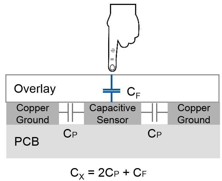
Fig. 2: Self-capacitive sensor with finger touch.
CX = Total self-capacitance of capacitive sensor
CP = Parasitic capacitance
CF = Capacitance added by a finger touch
Capacitive-sensing circuitry converts the measured capacitance to a digital count called raw count (Fig. 3 ). The raw count value of a sensor may vary gradually due to environmental changes such as temperature and humidity.
Therefore, the algorithms used to evaluate sensing events need a reference — also known as a baseline — to keep track of and compensate for gradual changes in raw count. Through the use of a baseline, algorithms are less sensitive to sudden changes in the raw count caused by a sensing event.
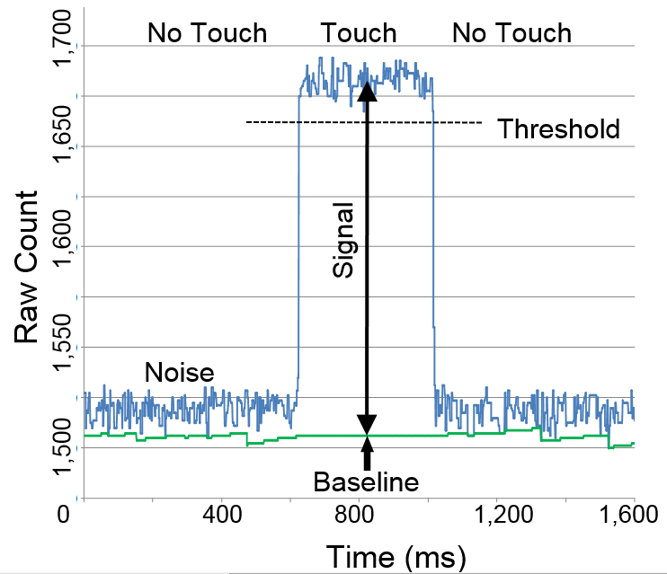
Fig. 3: Raw count variation on finger.
A finger touch or presence of a liquid increases the self-capacitance of the system, which, in turn, increases the raw count. An increase in the raw count above a user-defined threshold registers a touch or presence of liquid. The difference between the raw count when touched and the baseline is called the signal.
A mutual-capacitive sensor is used to measure the capacitance between two electrodes, Tx (Transmitter) and Rx (Receiver), connected to two pins as shown in Fig. 4 .
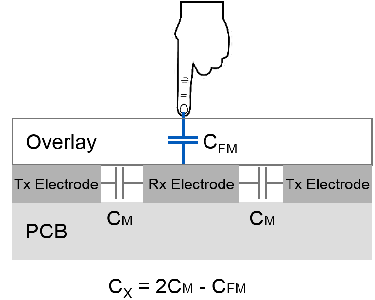
Fig. 4: Mutual-capacitive sensor with finger touch.
CX = Total mutual capacitance between the Tx and Rx electrodes
CM = Mutual capacitance
CFM = Mutual-capacitance reduction due to finger touch
Capacitive-sensing circuitry converts the measured capacitance to a raw count. A finger touch or the presence of liquid decreases the mutual capacitance of the system, which, in turn, decreases the raw count.
The raw count is normalized — after being subtracted from a given maximum value — in the post-processing phase to ensure that it increases during a sensing event. An increase in the raw count above a user-defined threshold registers a sensing event.
In Part 1 of this series, we discussed two different types of liquid-level sensing methods: point- and continuous-level sensing. We also discussed a few popular liquid-level sensing methods and their limitations. In Part 2, we will explore how point-level sensing is implemented using capacitive sensing. We will also describe when to use self- and mutual-capacitance-based sensing methods.
Advertisement
Learn more about Cypress Semiconductor


