BY SUBBARAO LANKA, Senior Staff Applications Engineer, and
SHRUTI HANUMANTHAIAH, Staff Applications Engineer
Cypress Semiconductor
www.cypress.com
In Part 1 of this article, we explained popular liquid-level sensing methods and their limitations. We also delved into why capacitive-sensing techniques are superior to traditional methods used for liquid-level sensing.
Here, we will explore how capacitive sensors can be implemented in both point-level and continuous-level sensing applications. But first, let’s have a look at how capacitive sensors work in a liquid-level sensing system (Fig. 1 ).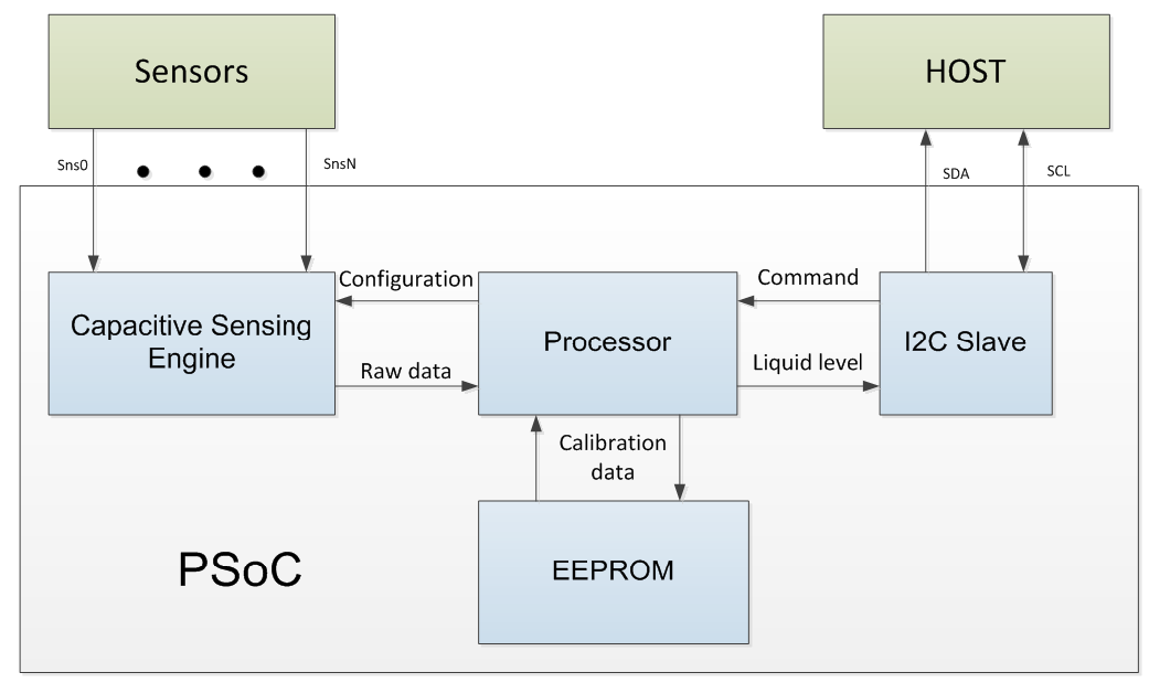 Fig. 1: Block diagram of a liquid-level sensing system.
A microcontroller — such as the Cypress PSoC — takes capacitive sensor inputs and computes the liquid level with the help of the CPU and a capacitive-sensing engine, called CapSense in the PSoC jargon. The liquid-level information is then sent to the system host for further action while the calibration data is stored in EEPROM.
Implementing point-level sensing
Point-level sensing uses one or more sensors placed at discrete levels on the tank according to application requirements. This sensing approach relies on the on/off state of the individual sensors to determine the liquid level.
Fig. 2 shows a tank with one sensor attached to it at the bottom for empty-level detection. The tank-empty status is determined based on the sensor’s on/off status. When the tank is not empty and is filled with conductive liquid, the sensor will be on. And when the tank is empty, the sensor will be off.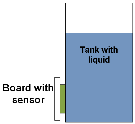 Fig. 2: Capacitive sensor for empty-level detection.
It’s important to note that in point-level sensing operations, the sensing itself requires a reference. If the reference is incorrect, sensing will be inaccurate. In capacitive-sensing methods, the baseline is the reference.
In general, with capacitive sensing-based implementations, for a user interface, the system assumes that no finger is touching the sensor at power-up. So the baseline is initialized using the sensor characteristics, primarily the parasitic capacitance — the sensor capacitance with respect to the system ground.
But setting a baseline is not as simple as developing a user interface when it comes to liquid-level sensing. When there is no liquid at power-up, the sensor is off, indicating that the tank is empty. And when the tank is filled with liquid, the liquid adds capacitance and the sensor will be turned on, indicating that the tank is not empty.
However, when there is liquid in the tank at power-up, there can be problems, especially regarding the raw count — when capacitive-sensing circuitry converts the measured capacitance to a digital count. Because raw count measured at power-up is used as a baseline reference, the sensor will be reported as off, indicating that the tank is empty when it’s not.
There are two ways to resolve this issue: the reliable reference method and the calibration method.
Reliable reference method
This method is carried out using a virtual sensor that boasts similar characteristics as the sensor utilized for detecting the liquid level. However, it’s not placed in direct contact with the liquid. In other words, this sensor must remain unaffected by the liquid level.
The raw count of the virtual sensor can then be used as the reference for the actual sensor as both of these sensors possess the same physical properties and, ideally, have the same baseline. Let CX be the capacitance of both the virtual sensor and tank-empty detection sensor without liquid. And let CL be the capacitance added by the liquid.
Without liquid:
Virtual-sensor capacitance = CX
Tank-empty detector-sensor capacitance = CX
With liquid:
Virtual-sensor capacitance = CX
Tank-empty detector-sensor capacitance = CX + CL
The difference in the capacitance (CL ) of the tank-empty detector sensor and the virtual sensor is measured to detect whether the tank is empty or not.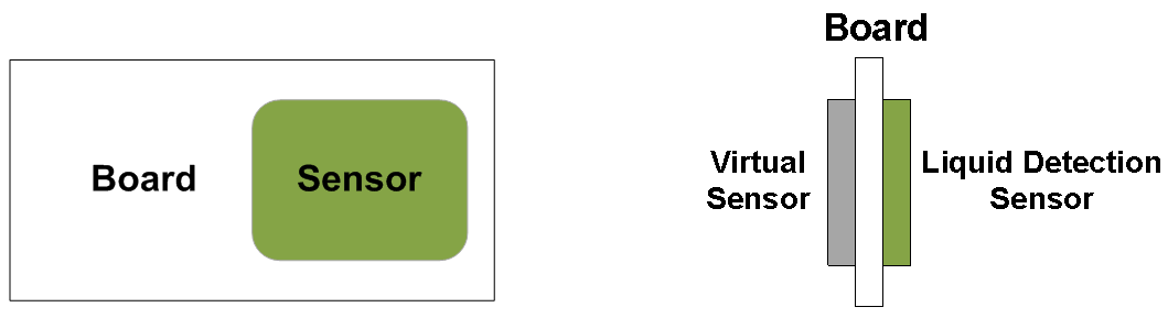 Fig. 3: Board with virtual sensor showing the front view (left) and side view (right).
Designing a virtual sensor can be a challenge for layout designers. A rule of thumb is that, while designing the virtual sensor, the capacitance of the sensor used for detection and the virtual sensor should be the same. To achieve this, the following layout recommendations are suggested:
• Virtual sensor dimension: It should be the same as the sensor used for liquid-level detection.
• Sensor trace length: It should have the same trace length as the sensor used for liquid-level detection. However, trace length can be varied to match the capacitance.
• Number of vias: It must be the same as the sensor used for liquid-level detection. In order to reduce overall parasitic capacitance, the number of vias must be limited to three at most.
• Sensor placement: The virtual sensor and the sensor used for liquid detection must be placed on different layers of the PCB.
Calibration method
It requires the sensor to be calibrated in the factory before being used for sensing. The raw count of the sensors with and without liquid should be stored in EEPROM. Next, after completing the calibration, the run-time raw count of sensors is compared with the stored raw count to decide the sensor’s on/off status.
Implementing continuous-level sensing
Take the example of a coffeemaker using continuous-level sensing with a capacitive sensor. The continuous-level liquid sensing requires a sensing board primarily comprised of a transmitter (TX) and “n” receiver (RX) sensors, whereas “n” is the number of receiver sensors. This value depends on the height of the tank and the resolution of liquid-level sensing required. Fig. 4: Liquid-level sensor stack-up.
The sensing board is placed vertically on the side of the tank as shown in Fig. 4 . Sensing can be done in firmware, with additional techniques if necessary, to meet the system-level requirements such as accuracy, linearity, response time, and power consumption.
Calibration is necessary to get an accurate signal corresponding to empty and full tank. Calibrating when the tank is full and when the tank is empty is termed as two-point calibration.
Moreover, in order to reduce the influence of external factors like temperature, the calibration procedure should consider multiple samples of emptysignal and fullsignal . Here, 256 has been found to be a good number of samples. Each fullsignal sample is an average of the fullsignal of all individual sensors.
Similarly, each emptysignal sample is an average of the emptysignal of all individual sensors. After 256 samples are collected, the average of all of these samples is taken and stored as calibration data. In the calibration procedure, while the recommended number of samples is 256, the number of sensors amounts to 13.
Advertisement
Learn more about Cypress Semiconductor


