Since any measurement is only as good as the weakest link in the test system, poor switching will give poor measurements
BY BOB STASONIS
Sales & Marketing Manager
Pickering Interfaces
www.pickeringinterfaces.com
Automated test systems, or ATE, have many different elements, depending on the application, but signal switching is pretty much the norm in almost all instances. No one switching systems works for all applications, and the selection of the right system components is important.
Selecting the right signal switching is more important than most test engineers give it credit for. Signal switching is responsible for the connection between the unit-under-test and all the stimulus and response instrumentation (see Fig. 1 ). A proper connection ensures that the system is repeatable and accurate. Since any measurement is only as good as the weakest link, if you pick poor switching, you will get poor measurements.
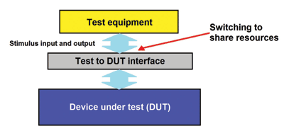
Fig. 1: This simplified block diagram emphasizes how signal switching is a critical element of the test system, gating access of test equipment resources to the device under test.
Since wrong decisions in switching can affect system reliability and accuracy, putting a little forethought into your test system design can reap tremendous payback. In this article, the questions raised will apply not only to test systems based on the widely used PXI , but to every other test platform commonly used in our industry today.
First questions to ask
When designing a tester with signal switching, it’s important to make very careful choices. First, assess the test plan and the unit-under-test’s design from a relatively high level. Then look at the test platform choices available and the resources available from inventory, and decide what will have to be purchased from approved vendors. The key factor in selections is accurate repeatable measurements and reliability of the system.
When it comes to the test system’s switching systems, there are a number of questions to ask. To begin choosing the switching system, start with the basics: the relay types. The relay types available for various applications are important for both accuracy and long test-system life. If someone could invent one relay to work from dc to 26 GHz and handle 10 A to 50 mA repeatedly, that person would be very wealthy. But in reality, there are many choices that are application dependent.
A so-called reed relay (see Fig. 2 ) provides longer switching life and provides safety in harsh environments, for instance, where there are flammable gases. The reed has a coil wrapped around to actuate the switch magnetically.
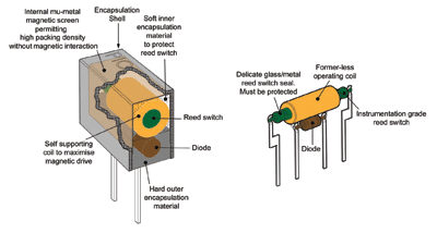
Fig. 2: In a reed relays, a switch is enclosed in a glass capsule, or “reed”, that protects the electrical contact.
The primary advantage of reed relays is reliability: They are often good for 108 operations or more, and exhibit lower thermal EMF than other types of relays. Thus very-low-level-signal applications requiring very high accuracy are a good fit for reeds. The downside is they have a higher cost, and their hot-switching specs are not as good as other relay types. (More about hot switching later.)
Another very popular relay type is the electromechanical relay (EMR, see Fig. 3 ). The advantage of EMRs is that they can have larger gap between the contacts when open, allowing for a lot higher voltage to be switched by these devices. They can also have larger contact area, which means they can handle much higher current switching. Finally, EMRs are much lower cost than reeds, as they are simpler to manufacture. Their disadvantages are that they have a shorter life and tend to have a high thermal EMF.

Fig. 3: Note that, unlike reed relays, electromechanical relays have no encapsulation of the contacts, which therefore are exposed to the environment.
Solid-state switching is seeing more popularity in test and measurement lately. A solid-state relay technically has unlimited life if you stay within the specifications; they just don’t wear out. Also, they also have no switch bounce.
On the other hand, solid-state relays have very narrow bandwidth compared to reeds and EMRs. They can also have a high resistance in the closed operation when compared to mechanical relays. There are voltage limitations and leakage issues as well. But for many applications, solid-state switching has a very good fit in certain areas.
Test planning
With a knowledge of relay types, it time to get into the actual test plan. Here are the questions to be answers:
What specifications do you need to be testing?When switching a signal source or taking a measurement, what is the maximum voltage will be dealing with?What is the highest current to worry about and at what frequency?
Armed with the answers to these questions, we can consider whether hot or cold switching (also referred to as switch or carry current, respectively) is needed. Basically, it means whether the relay will be switched with power applied (hot) or first closing and then power applied (cold). The specs of most relays will be different for hot and cold switching.
Next steps
Once the relay type has been determined, the switching configuration must be determined. The choices are simple SPST relays, multiplexers, or crosspoint matrices. Then the number of test points to be controlled must be considered.
At higher frequencies, you will likely have added requirements such as how much reflective power can be tolerated, what is the worst-case insertion loss, and so forth. Finally, consider the environment the test systems will be in. Will there be explosive vapors? For example, are you building a tester to go on the flight line in an airport or a military base?
Cabling is probably equally important, because you can have a very good switch that has very low insertion loss and the repeatability and life you need, but the cables are too small, are the wrong type of coax, or have very-low-quality connectors. You suddenly lose the advantage you have of the switching module. In which case, the cables become the weakest link in your test system, affecting all measurements.
Avoiding failures
Even though you’ve decided what type of relays, modules, and configurations are required, you still need to focus on what can cause failures, in the hopes of avoiding them.
The first thing to consider is hot switching. Hot switching degrades all mechanical relays, even reed relays or EMRs. The relay’s datasheet will give you several numbers for expected life — for low, medium, and full power and you’ll see a very big difference in the life of that relay at each step. Also, if you’re running very close to the relay’s limits, you can potentially damage the relay and even set it on fire!
The next issue of concern should be if the circuit itself is a high-capacitance load. There are applications where you may deliberately or inadvertently need to discharge a large amount of power; one example is when you change polarity. This can create high surge currents and they do affect the life of your switching. Obviously you can’t always avoid this situation, so you may have to factor in higher-capacity relays in this case.
Another area that happens mainly during development is code errors that could leave a relay closed too long, or you accidentally hot-switch the circuit that you had planned to cold-switch. We all make mistakes, so thoroughly verifying and validating your code is important.
Another area where the relay specifications can be overlooked is the power rating. Relays often have a power rating that is not always as high as you might think. Many test-and-measurement switching systems assume a low duty cycle, so it does not consider continuous power.
You might think that minimum voltage is not a problem. Think again, especially for high-voltage applications, where most high-voltage relays must have a minimum voltage to switch reliably. If you try to switch lower voltage, you may get a very high resistance because the contacts are not “wetted.” Wetting is important in EMRs, as the contacts are exposed to the environment and can oxidize. (See “On ‘Wetting’” below)
Another specification to watch out for is the expected life of the relays. If you have an application that will be tested for many months or even years, you will want to go for the highest life rating possible. Otherwise, plan into your test cycle some kind of downtime and maintenance for replacing switching modules that have reached the end of their life (see Fig. 4 ).
On “Wetting”
For those of us who have been in test for WAY too long, the term “wetting” initially applied to relays whose contacts were immersed in, or “wetted” with, mercury. Such relays were used to switch signals where the mercury reduces the contact resistance and associated voltage drop. For low-current signals, the mercury would prevent surface contamination that may make for a poor contact; for high-speed applications, the mercury would eliminate contact bounce.
Of course, because of the toxicity of mercury, we rarely see mercury wetted relays any more. So we make do with other technologies.
Today wetting refers to a minimum current passing through the relay. Wikipedia provides a good definition of wetting current: “Wetting current is the minimum current needed to flow through a mechanical switch while it is operated to break through any film of oxidation that may have been deposited on the switch contacts. The film of oxidation occurs often in areas with high humidity or chemical vapors. Providing a sufficient amount of wetting current is a crucial step in designing systems that use delicate switches with small contact pressure as sensor inputs. Failing to do this might result in switches remaining electrically ‘open’ or higher than allowed resistance due to contact oxidation.”
This means that if your test setup exhibits random low values of resistance or even opens, look closely at the specs of the relays used. It is possible that your circuit does not have enough wetting current to cut through any oxidation. This may mean that you need to change the relay type in your test, better control the environment the ATE is in, or add circuitry to “wet” the relay prior to test.
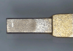
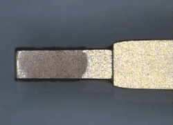
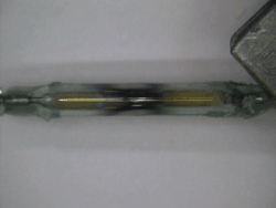
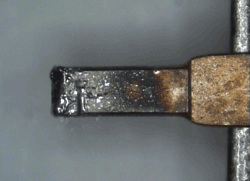
Fig. 4: Relays can require you to plan for maintenance. The two top disassembled reed relays illustrate normal wear and tear; the uppermost one is a new “clean” reed contact while the one beneath it is a little bit darker from use, but still within specifications. In the third photo from top, the contact has been welded shut from misuse, while the one below it is pitted and will be very unreliable.
What’s broken?
Let’s suppose that we have a crosspoint matrix with a bad relay, one that’s either stuck open or closed. You’ll see multiple crosspoint failures because of the way a matrix works (see Fig. 5 ). The problem is to find the fault among 8,000 relays.
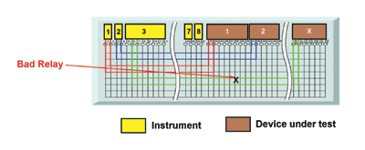
Fig. 5: One bad relay in a matrix can actually affect many possible connection. Detecting it from the edge of the matrix is the challenge.
Let’s first consider self-test in the area of switching. Several factors limit added self-test, among them added cost. While the defense industry may be okay with this, many commercial industries balk at added costs. With standards like PXI, you also have the issue that the small PCBs don’t allow much room to add self-test. Still, we can find ways to make it work.
Commercially, there are tools for testing the switch paths. The primary method in many cases is an external tool that connects a DMM to basically check for shorts and opens along all the paths of a complex switch system. An external tool would connect up to the front panel and basically characterize all switch paths of a matrix or multiplexer.
This works for a relatively complex module. If the board only has 20 or 30 relays on it, vendors might not offer a solution because of the simplicity. You could put a lot of time and effort into developing an automated solution that may not be worth it.
In any case, the tools should identify faulty relays. The obvious faults mentioned earlier are stuck open and stuck closed. But you also need to consider borderline connections. Once again, a DMM can measure the resistance of the path and look for borderline relays that are starting to get outside of the specification.
It is important to ensure that the tool logs test results, as you can then analyze long-term failures. Remember mechanical relays do wear over time, even when not stressed; as they get close to end of life, their resistance will go higher. You can look at these log files and analyze the trends with the thought of changing particular relays because they’re getting close end of life.
For the self-test configuration in Fig. 6 , if I close one relay, I get path through one 47-Ω resistor in the x axis and one in the y. Thus a good connection will present a 94-Ω reading on the DMM. If a relay was stuck open, the measurement would be out of tolerance. If another relay was stuck closed somewhere in the matrix, you get a parallel path across the 47-Ω resistors and that will change the measured value. Multiple measurements with different relays open and closed will pinpoint the failed relay.
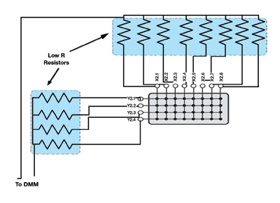
Fig. 6: To configure a basic 4 x 8 matrix with a self-test fixture requires a series of high-accuracy 47-Ω resistors. One end of each resistor is connected to the x-axis or the y-axis and the other end connected in parallel with other 47-Ω x or y resistors to a DMM.
As previously mentioned, certain high-voltage relays like to have a higher voltage to wet the contacts. So be careful of this type of self-test if using a DMM, since on average they source about 5 V at 1 mA for measurement, which will not be enough to wet the relay contacts. Any high-voltage relays in your application may need a high-voltage source applied and you would measure the voltage drop across the relay.
Another possibility is to look at vendors who have built-in self-test for their products. Thanks to advances in technology, there are vendors pursuing the philosophy of building in a self-test at very reasonable costs. One method is to provide an ac source connected to the path. The voltage drop is measured by an ADC and accompanying software makes path closures and verifies the voltage drop, assesses whether the path is correct or out of tolerance, and notes the result before moving on.
Of course, there are always alternatives. One technique of self-test has been used for several years is called “relay counting.” The premise is that every relay has a certain operations life, and that counting the number of times the relay is closed will indicate when it is at the end of life.
While this sounds simple, it’s fraught with problems. First, relay counting does not take into account the impact of switching current on the relay life. Relay lifecycle depends on the load across the contacts: At very low current loads the relay may operate to the rated count, but full power wills reduces that count. Relay life could be reduced by at least three orders of magnitude in some applications. So whether or not relay counting will work is heavily dependent on the actual usage. ■
Advertisement
Learn more about Pickering Interfaces


