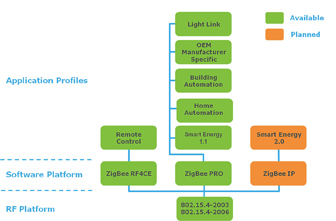
ZigBee profiles define application-level communication protocols that provide interoperability between devices and applications from different vendors. Profiles are based on a number of target application areas such as smart energy, healthcare, telecom, and, most recently (April 2012), lighting. To also ensure networking interoperability it is required that ZigBee profiles are implemented on top of ZigBee PRO–compliant networking stacks. In this way most networking characteristics are determined by the underlying protocol and are similar for all application-based profiles. The ZigBee PRO standard uses license-free 2.4-GHz frequency band with a 250-Kbit/s physical data rate and specifies important mechanisms for networking such as security, mesh routing, and network management. Figure 1 illustrates the family of ZigBee protocols and profiles.

Fig. 1: ZigBee profile family tree.
To achieve interoperability on the application level, ZigBee profiles rely on the concept of clusters. A cluster defines a standard interface to a common functionality, for example, time, on/off, and level control. It specifies how a particular functionality should be maintained on the node (server side) as well as the protocol commands required for other nodes to access this functionality.
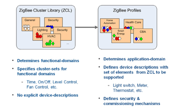
The ZigBee Cluster Library (ZCL) provides definition information for all the ZigBee profiles. Each ZigBee profile specifies device types that operate within the application area. For example, the Smart Energy profile defines metering device, energy display, thermostat, and others (see Fig. 2 ). The Light Link profile defines access to devices such as on/off sensor, light dimming, and light color. For each device type there is a list of mandatory and optional clusters to support. The same clusters are often used in different ZigBee profiles, allowing devices to be interoperable across more than one application profile.

Fig. 2: The principles of ZCL and ZigBee profiles.
Industry lighting leaders such as Philips, Osram and GE, together with ZigBee chip vendors, drove the design of the ZigBee Light Link (ZLL) profile. The ZLL profile specifies two main groups of devices: controllers (e.g. sensor, bridge, remote controller) and lighting devices (color light, dimmable light. etc.). An important part of the ZLL profile design is to ensure ease of installation and use of the devices without any prior technical knowledge. This is achieved by providing a thorough description of device commissioning procedure, extensive test coverage, and the absence of any optional functionality that can lead to interoperability issues.
A ZLL network is formed and operated in a distributed manner. There is no need to have a central coordinator node that manages the network and communication. This makes the system easy to install and maintain as well as making it very robust, as there is no single point of failure.
On the light manipulation side, the ZLL profile standardizes control of the on/off state, color hue, saturation, brightness, and color temperature. It also allows configuring light parameters as a “scene” and recalling them, as well as organizing lighting devices into groups controlled simultaneously. This is achieved by using Color Control, Level Control, On/Off, Scenes, and Groups clusters.
Light Link–controlled devices can interoperate with home automation (HA) devices if they are joined to the same ZigBee network. Using this approach, ZLL lighting devices can be controlled both by ZLL controller devices as well as HA devices. Such communication is possible since HA and ZLL profile use the same clusters (although clusters used by ZLL may have additional attributes), and the connections between devices are established using the standard ZigBee mechanisms.
A new lighting device is added to a ZLL network via “touchlink” commissioning. To initiate this procedure, a controller device and a lighting device are put close to each other (typically within 20 to 50 cm), and the user presses a button on a controller that instigates a command exchange. During this step, network parameters are transferred to the lighting device, after which it becomes attached to the controller's network. This operation is repeated for each new lighting device that has to be manipulated by the controller.
Usually ZLL controllers use group addressing by default. After touchlink the light is added to a controller's group. Group addressed commands from the controller reach all lights. It is also possible for user to select a specific light to be controlled individually.
As a ZigBee end device, a controller sends all frames to the network via its parent router. A lighting device, as a router then forwards these frames to the destination nodes, if needed using other intermediate routers. If the path to the final destination is unknown on some of the nodes then a route discovery procedure is automatically initiated within the stack and best suitable path will be used to deliver the message. From the application level only address of the target node shall be specified. Path discovery and maintenance (if conditions change or some routers are removed) is handled automatically inside ZigBee stack.
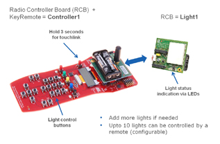
When considering incorporating ZigBee Light Link into a new product, engineers can use a reference design available from many microcontroller suppliers. For example, Atmel's RF4CE-EK evaluation kit uses a solution based on their ATmega128RFA1 wireless SoC device using a ZigBee PRO stack called BitCloud (see Fig. 3 ). Within the kit, a reference application called 'ZLLDemo' contains certified implementations of a color light and a color scene controller.

Fig. 3: BitCloud ZigBee Light Link demo with light control.
Performing a touchlink between a controller and the light device forms a network. When the the light unit identifies itself identification is done either by flashing the LCD screen or blinking with the LED.
Once lights are commissioned to the network, the lights can be manipulated using numerous buttons present on the remote controller. Commands for on/off, brightness, and color, as well as scene setup are available for user. They can be sent to the lights as groupcast or unicast.
Nodes save current networking and application parameters into EEPROM and, in case of reset or power cycle, restore their network state and do not need to be re-commissioned into the network again.
Advertisement
Learn more about Atmel, USA


