BY RON BERTHIAUME, Principal Applications Engineer,
SHAHIN MALOYAN, Power Applications Engineer
Exar
www.exar.com
The principle of Constant On-Time (COT) has been used as a control method for buck, or step-down, regulators for many years. As a technique it has a number of advantages over standard, fixed-frequency, pulse-width modulation (PWM) schemes, offering a fast response time and a solution that is simple and inexpensive to use because it doesn’t require complex external frequency compensation.
However, COT does have some disadvantages with respect to output voltage (VO) accuracy and its dependence of circuit parasitics. The method is also prone to jitter and can exhibit frequency variation during transients. This article looks at an improved COT controller design that addresses the concern of VO accuracy, removes the dependence on circuit parasitics, and delivers a fast transient response.
Understanding standard fixed-frequency PWM control
Conventional fixed-frequency PWM control relies on the duty cycle of the switching frequency to control the on time of the switching device, which is typically a MOSFET. This is achieved using a linear error amplifier, which compare the output voltage (VO) with a reference voltage (VREF) to control the pulse width. The resulting pulse width is continuously variable and, to ensure stability, the error amplifier requires good frequency compensation.
There are two main types of fixed-frequency PWM; trailing edge control and leading edge control, of which trailing edge is the most common implementation.
Trailing edge fixed frequency PWM regulation
The circuit schematic and associated images are shown in Fig. 1 . As can be seen, the output from the error amplifier (EAO) is compared to a sawtooth waveform (Vramp), which ramps from low to high and then immediately drops back low. Hence the on time for the switch commences on the trailing edge of Vramp, with a duration that lasts until the ramp voltage equals the error voltage. Note that the frequency of Vramp is fixed and determined by the switch clock.
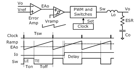
Fig. 1: Trailing edge fixed frequency PWM regulation
One advantage of trailing edge fixed frequency PWM is that it is well understood because it has been so widely employed in current and voltage mode regulators. It also provides good accuracy. Its disadvantages lie in the complex frequency compensation required and the delay experienced in responding to a step increase in load current (IO), that is, the delay from when the current increases during the switch off-time until the switch is turned on at the beginning of the next cycle.
Leading edge fixed frequency PWM regulation
Here, as illustrated by Fig. 2 , the leading edge of the switch control signal occurs when the output from the error amplifier equals the falling ramp waveform and is turned off when that waveform returns high. Although less commonly used, leading edge fixed frequency PWM regulation shares the same advantages and disadvantages as the trailing edge implementation, except that the delay incurred is when the load current (IO) drops.
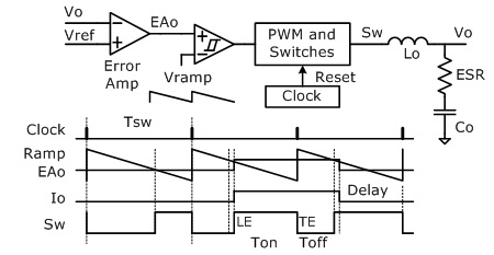
Fig. 2: Leading edge fixed frequency PWM regulation
The adoption of COT regulation
Constant on-Time (COT) regulation first became popular around 2003/4 in the notebook market due to its high light-load efficiency and simple implementation. Since then it has proliferated into many other markets, such as networking, communications, and industrial.
COT regulation uses a fixed on time and controls the duty cycle of the switching waveform (Sw) by varying the off time. In this respect the switching frequency is not fixed although it will remain fairly constant under constant load and input voltage conditions. As shown in Fig. 3 , VO is directly compared with VREF rather than comparing an error signal with a ramp waveform. In this way the output voltage is maintained close to the reference voltage, increasing slightly during the fixed on time and then decreasing during the off period as the load capacitor discharges until VO drops below VREF, at which point the comparator will turn the switch back on again, starting the next cycle.
COT regulators like this do not require the external frequency compensation of fixed frequency PWM designs but do require the effective series resistance (ESR) of the output capacitor to be higher than that offered by most modern day ceramics. Usually polymer aluminum electrolytic capacitors with 20 to 30 milliohms (mΩ) of resistance work well with a standard COT control loop. Consequently, a COT circuit is almost more concerned with regulating the ‘valley’ of the output voltage, not so much the average voltage.
In summary, a COT regulator provides a very fast transient response and is simple and inexpensive, and doesn’t require complex external frequency compensation. It is however jitter prone and sensitive to the ESR of the output capacitors. Standard COT designs also suffer from dc offset errors in the output voltage and frequency changes during load steps.
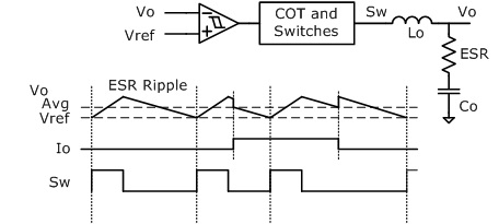
Fig. 3: A standard COT regulator
Improved COT controller with emulated ESR and dc correction
Figure 4 illustrates a simple modification to the design of a COT controller, which overcomes its sensitivity to ESR value and eliminates any dc offset error in the output voltage. Like established COT regulators, this circuit remains very simple and inexpensive and still delivers a very fast transient response although frequency changes during load steps are unavoidable.
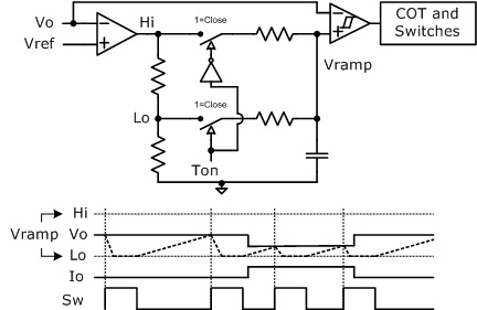
Fig. 4: Improved COT controller
Like the fixed frequency PWM regulators described earlier, this improved COT controller amplifies the error between VO and VREF but that is where the similarity ends. The output voltage from this amplifier is split to provide Hi and Lo limits for a ramp waveform, generated by the on time pulse (TON). It is this signal which, when finally compared with the output voltage VO, counteracts the ESR and dc offset effects associated with a standard COT controller. Additionally, unlike other schemes that sum a ramp into the VO signal, by adding the ramp to the reference there are no delays introduced into the response.
COT regulators offer considerable benefits over the previously established fixed frequency PWM regulators, which require complex external frequency compensation and suffer from response delay following step load changes. Until now COT regulators, while offering excellent transient response, suffer from sensitivity to the effective series resistance of load capacitors and output dc-offset errors. The improved COT controller design outlined here uses ESR emulation and dc correction to overcome these problems. Exar has implemented this improved COT architecture in all its recent COT Controller devices including its latest XR75100 40-V COT Controller, which achieves 0.008%/V line regulation making it ideally suited to point of load (PoL) applications.
Advertisement
Learn more about Exar


