There are several important considerations when implementing S-GPS in single-antenna multiband CDMA handsets
BY ALLEN CHIEN and WON KYU KIM
Avago Technologies
San Jose, CA
http://www.avagotech.com/
Establishing the location fix of an E911 call from a CDMA mobile phone is typically accomplished using a built-in GPS device. Handset-based GPS receivers to date have mostly worked using a time-multiplexed scheme (TM-GPS), where the GPS signal and the telephone call signal sequentially toggles back and forth. This method is attractive because only one RF radio is working at a time and is easy to implement.
Simultaneous GPS comes to the fore
Simultaneous GPS (S-GPS), where both GPS and telephone call operate simultaneously, is becoming increasing common because it provides ~4-dB improved sensitivity and enables location-based services (LBS) for service providers. S-GPS-capable chipsets from manufacturers such as Qualcomm have been commercially available since 2004 and are being widely adopted in today’s CDMA handsets.
A single antenna is preferred whenever possible because of lower costs and smaller space use. Figure 1 illustrates a generic block diagram for the GPS receive chain in a single antenna tri-band phone.

Fig. 1. In a single-antenna tri-band phone, the GPS receive chain often looks like this.
The GPS receive chain consists of a GPS filter, a low-noise amplifier (LNA), an inter-stage filter, and down converter with each component contributing to the overall system sensitivity. The term GPS sensitivity is defined as the lowest signal power level at the antenna port where the handset should be able to locate the GPS satellite 98% of the time.
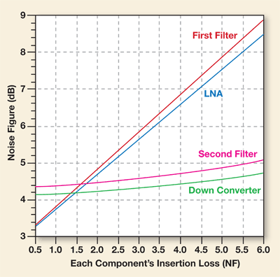
For both TM and S-GPS operation, important variables contributing to system sensitivity are the first GPS filter’s IL and LNA NF, while the second GPS filter’s IL and down-converter NF have minimal affect. Figure 2 illustrates how the total system noise is impacted by each of the discrete components.

Fig. 2. A plot of system noise versus each component’s insertion loss, or noise figure, shows the importance of first GPS filter IL and LNA NF.
Since the first filter’s insertion loss (IL) and LNA NF directly affect the GPS system noise, those values should be minimized during component selection. Filter IL is governed by the quality factor, Q, of the filter, with the higher the Q the better. Of the two filter technologies used in cell phones today, surface-acoustic wave (SAW) and film bulk acoustic resonator (FBAR), FBARs have, in general, demonstrated higher Q and lower IL.
Out-of-band jammers
A new factor with S-GPS is that the GPS receiver chain will experience high-strength out-of-band jammers that may saturate the GPS receiver and degrade sensitivity. TM-GPS does not experience this problem since the radios operate only sequentially.
The most important out-of-band jammers are the PCS/Cell-band Tx signal leakage and Tx + Jammer cross-modulations signals. Rejection of these signals is critical to prevent LNA gain compression and preserve good system sensitivity.
To achieve maximum GPS sensitivity, it is recommended to choose the best possible IL filter and IIP3 LNA values available and trade off as much out-of-band Isolation as possible. The post-LNA (second GPS) filter should be selected to emphasize its out-of-band rejection characteristics over IL, since its primary function is to block any jammers that get amplified by the LNA.
These post-LNA blockers could contribute to IMD2 products in the down converter. The amount of IMD2 products should be minimized because they can act to demodulate the AM component of the signal as it gets down-converted to the baseband level, which results in degraded bit-error rate (BER).
Two solutions for tri-band phones
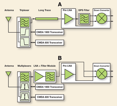
Figure 3 examines two solutions for single-antenna tri-band phones. Solution one uses a triplexer that has ~1.8-dB GPS IL and a long RF trace to connect it to the LNA, which contributes additional loss, and 48-dB isolation to CDMA Tx jammers.

Fig. 3. Block diagrams of the GPS receive chain using (a) triplexer + discrete GPS filter solutions and (b) a highly-integrated ACFM-7102 multiplexer and ALM-1412 LNA filter module solution.
The built-in LNAs in the transceiver chips often have IIP3 values close to 0 dBm. The combination of the above filter and LNA values usually results in 0.2-dB gain compression of the LNA and the noise figure of the first two stages becomes ~4.1 dB.
The inter-stage GPS filter rejection of 47 dB becomes insufficient to prevent down-converter gain compression further downstream. The total system gain and NF of this solution are 38.97 and 4.49 dB, respectively. The expected overall GPS sensitivity of this system is –155.4 dBm, which may be insufficient to meet E911 accuracy requirement (50 m for 67% of the calls) when used in conjunction internal antennas.
Improved GPS sensitivity is expected if the multiplexer solution is used as shown in Fig. 3b . The first GPS filter in the multiplexer has a lower IL (~0.9 dB) and better than –52 dB of isolation to both CDMA Tx channels. An external GaAs LNA filter module can then be positioned next to the multiplexer GPS port so no additional loss is experienced due to long RF line lengths. The LNA filter module utilized has 54-dBc rejection, 0.8-dB NF, and an improved linearity value of 5-dBm IIP3.
The resulting overall system gain and NF then become 40.06 and 1.97 dB, respectively. This solution has enough rejection to the CDMA Tx jammers, such that there is negligible gain compression in the LNA and down converter and the expected overall GPS sensitivity is roughly –157.6 dBm. This improvement of 2 dB in GPS sensitivity provides a solution that should be sufficient for satisfying E911 requirements when using an internal antenna.
S-GPS architectures enable sensitivity improvements over TM-GPS architectures and enable LBS. However, simultaneous use of GPS and CDMA radios imparts new constraints to component selection used in the phone.
The main new consideration is rejection of strong out-of-band jammers such as Tx signal leakage of the Cell or PCS Tx chain. The two most important factors in GPS sensitivity are first-stage GPS filter loss and LNA NF.
Using an LNA with good linearity and selecting filters with sufficient rejection to CDMA Tx channels are required to prevent gain compression of the LNA. Two GPS receiver architectures are presented with the highly integrated, compact multiplexer/GPS LNA filter module solution demonstrating a 2.2-dB GPS sensitivity improvement over the triplexer solution. ■
Advertisement
Learn more about Avago Technologies


