BY WILLIAM SHENBERGER, Field Applications Engineer
Littelfuse, Inc.
www.littelfuse.com
Designers of early indoor LED light bulbs faced numerous technical hurdles, including AC-to-DC conversion, thermal heat-sinking, constraints imposed by current bulb sizes, electrical transients, and not to mention the basic challenge of driving the LEDs that produce the light. Providing protection from transients for both the LEDs and all of the components upstream from them in the circuit represents a significant design challenge. These transients often result from lightning-induced surges on the AC input. LED bulbs require both overcurrent and overvoltage protection from these threats.
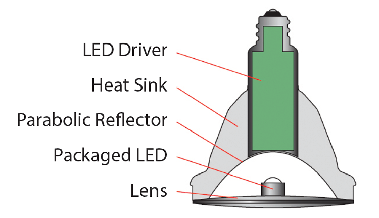
The demand for added functionality and higher light output has increased the number of LED board components. Higher light output creates a demand for larger heat sinks to increase heat dissipation. Because LED bulbs must be form-factor-compatible with current incandescent and CFL bulbs (such as the A19 household bulbs), they include an AC/DC power supply circuit so that they can operate from standard bulb sockets (Fig. 1 ). Anything directly connected to an AC power source can be damaged by short-circuit and overload conditions caused by component and/or circuit failures inside the bulb. In addition, lightning surges or load switching transients (originating outside the bulb) can create voltage spikes or ring waves that can stress and ultimately damage components inside the bulb.

Fig. 1: Construction of a typical residential LED lamp.

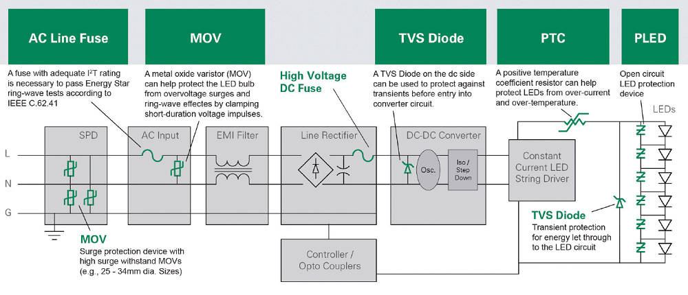
Fig. 2: Typical LED luminaire driver circuit with transient and surge energy protection devices.
The AC line fuse is the bulb’s primary overcurrent protection device. When properly selected, this fuse will adequately protect all downstream components from electrical overstress (EOS) damage by safely disconnecting all circuitry from the AC line input.

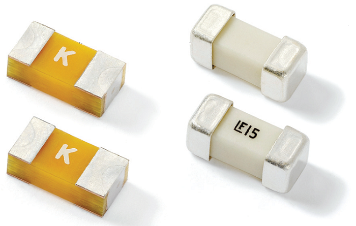
Fig. 3: Fast-acting subminiature surface-mount fuses, like the Littelfuse NANO2 470 and 476 Series, provide surge tolerance and circuit protection against overload conditions for downstream components.
Given the tight space constraints associated with LED bulb design, it is critical to select a highly compact AC fuse for the AC input. A fuse’s function is to provide protection for components and complete circuits by reliably and predictably melting under short-circuit and current-overload conditions. The right fuse in series with the AC line input will provide the needed protection. Today, AC fuses are available in the smallest of form factors with a wide choice of amperage and voltage ratings. A range of additional key parameters and surface-mountable designs are also available to allow design engineers to choose a fuse that will satisfy all of the requirements of the application.
The primary overvoltage protection (OVP) device for an LED-based light bulb is an AC input circuit metal-oxide varistor (MOV). When properly selected for all required design parameters, it will protect all downstream components from EOS damage from induced transients and ring-wave effects by clamping short-duration voltage pulses. MOVs offer a cost-effective way to minimize transient energy that could otherwise make its way into downstream components. Proper MOV selection is based upon a number of electrical parameters, including the voltage rating, peak pulse current, energy rating, disc size, and lead configuration.

Fig. 4: Thermally protected metal-oxide varistors (TMOVs), including the LV UltraMOV from Littelfuse, act as an AC input circuit’s primary overvoltage protection device for an LED-based light bulb.
LED bulb designers need to consider several circuit protection issues:
- Answer technical questions about the application such as: the bulb’s normal operating current, application voltage, ambient temperature, overload current level and length of time within which the fuse must open, maximum allowable fault current, and the pulses, surge currents, inrush currents, startup currents, and circuit transients. Littelfuse offers numerous design resources including the Fuseology Selection Guide: Fuse Characteristics, Terms, and Consideration Factors and the Littelfuse iDesign Fuse Selection Tool .
- Know early in the design process the market in which the bulb will be sold. Depending on the geographic locations where the bulb is intended for use, different standards will govern design and testing requirements.
- Determine the size limitations that might affect the fuse that can be used. Fuses are available in a variety of packages, but surface-mount designs are the most common form factor for LED bulbs. Smaller footprint fuses are now available to protect the AC input, some just half the size of the smallest fuses previously available.
- The fuse temperature generated by the current passing through the fuse increases or decreases with ambient temperature change. Remember, the fuse’s “ambient temperature” is not the same as the “room temperature.” Instead, ambient temperature is the air temperature immediately surrounding the fuse, which is often much higher than the room temperature. For ambient temperatures at about 25° C, it’s recommended that fuses operate at no more than 75% of their nominal current rating. Fuses are temperature-sensitive devices, so even small temperature variations can greatly affect the predicted fuse life when it is loaded to its nominal value (i.e., 100% of rating).
- Determine the application’s required breaking capacity (i.e., interrupting rating, I2 t). This is the maximum approved current that the fuse can safely interrupt at rated voltage. During a fault or short-circuit condition, a fuse may receive an instantaneous overload current many times greater than its operating current. Safe operation requires that the fuse remain intact and clear the circuit.
- Transient suppression must be considered at the beginning of the design process. Coordinate the fuse with the downstream OVP and the LED string driver circuit. The selected fuse must withstand the energy of the transient at the specified level so that the LED string driver circuit capabilities are not adversely affected. The AC input circuit fuse and MOV provide transient protection that allows the needed overvoltage clamping capability to occur without the fuse opening while safely protecting the downstream circuitry, resulting in minimal disruption to the LED string driver circuit, including the LED string itself.
- In cases in which the bulb’s operational circuitry is not able to survive the required transient event levels, consider adding a secondary TVS diode for OVP. This is a proven solution that further clamps the “let-through” energy from the MOV. For extreme cases, consider additional OCP/OVP devices (see Fig. 2 ) to provide even more robust circuit protection.
- Other design considerations, such as the coordination of the fuse with the overvoltage protection and LED driver, are also important.
- Allow sufficient time for thorough application testing and verification prior to production.
Conclusion
Investing the time and resources necessary to ensure adequate circuit protection from the earliest stages of an LED-based light bulb design project will be rewarded with successful products and satisfied customers. Thanks to the latest advances in AC fuses, MOVs, and TVS diodes, the next generation of LED bulbs might just be around until the next generation of designers arrives.
Advertisement
Learn more about Littelfuse


