These devices significantly optimize illumination efficiency at the expense of cost and PCB area due to the use of an inductor
BY DARIO NURZAD
National Semiconductor
Santa Clara, CA
http:\national.com
The Internet has become the most popular medium for sharing pictures and videos, and for social networking. This has caused a migration to larger-size and higher-resolution color displays, the backlighting of which demands higher power from the battery.
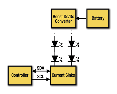
White light-emitting-diode (WLED) technology is widely used to provide illumination for the pixels in small-format liquid-crystal displays (LCDs) in battery-powered applications. Figure 1 shows a system-level view of a backlight LED driver that consists of an inductive-boost dc/dc converter and one or more regulated current sinks capable of driving one string of several white LEDs each.
How much PCB area will be needed? How is dimming achieved? Answering these questions can guide the designer in the selection of the appropriate backlight LED driver.

Fig. 1. A backlight LED driver consists of an inductive-boost dc/dc converter, and one or more regulated current sinks capable of driving one string of several white LEDs each.
Minimizing inductor size
The first aspect to consider, when selecting an LED driver for a battery-powered application, is the total area that the IC driver together with the external components will occupy.
A typical solution size for an inductive-boost-based LED driver is close to 30 mm2 of board area. Inductive drivers typically require two capacitors, one on the input and one on the output, with capacitor values of 1 to 2.2 µF that are available in 0603 and 0805 case sizes. They also require a rectification element that can handle the peak inductor current and output voltage. In a synchronous boost, a pass PFET can be integrated into the IC. However, this integration often causes the size of the IC package to increase over an asynchronous solution. The power conversion is also less efficient by about 10% in presence of an integrated high voltage PFET switch or diode. In an asynchronous topology, the pass element consists of a Schottky diode. The bulkiest component of the LED driver is the inductor which is also the tallest component in the solution.
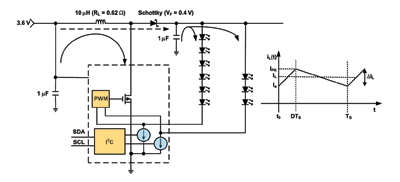
An inductor is a component that stores energy in the magnetic field of its core for release at some predetermined rate and at some predetermined time. Figure 2 shows the principle of operation of a magnetic boost regulator. When the NFET switch is closed (solid arrow), the inductor current iL (t) ramps upward from a minimum value Ia at t = 0 toward a maximum value of IPK at t = DTS , where TS is the switching period of the converter. During this time the Schottky diode is reverse biased and the load is supported by the energy stored in the output capacitor. At the end of this phase the inductor energy is equal to E = L x IPK 2 /2. The higher the stored energy the larger the required core, and hence the size of the inductor is proportional to its energy-handling capability.

Fig. 2. The principle of operation of a magnetic boost regulator is shown here.
At t = DTS the NFET switch is turned off and the energy stored in the inductor L is now delivered to the output capacitor and to the load (dashed arrow) through the Schottky diode. Consequently the inductor current ramps down during time ∆t2 DTS to the previous value of Ia . The output voltage must be greater than the input: if this voltage relationship were not true, the inductor would not discharge into the output network. In other words, when the NFET switch is turned off the voltage across the inductor is reversed because the current discharge can not occur instantaneously. The reversed magnetic voltage leads to the output voltage being higher than the input voltage. When driving ten LEDs in series the output voltage can be as high as 35 V.
The inductor value can be chosen such that a desired current ripple ∆IL is attained, and is given by L = (VIN x D)/(r x fS x IL ), where VIN is the input voltage, D is the duty cycle of the NFET switch, fS = 1/TS is the switching frequency, and r = ∆IL /IL is the inductor current ripple ratio.
In general, for a given application the inductance and size of the inductor can be reduced by increasing the switching frequency because the ac (∆IL ) and dc (IL ) components of the inductor current do not change. If the switching frequency is doubled, for example, the required amount of energy E = ½ x L x IPK 2 = ½ x L x (IL + ∆IL /2)2 , and thus the required size of the inductor is decreased by half.
Analog dimming control
The end consumer does not use the display of a handheld device 100% of the time that the device is turned on. For example, when a person is having a conversation on a cell phone, the display turns off after a short time.
The display brightness can be controlled directly by changing the LED current (analog control) or indirectly by shutting on and off the LED fast enough to create the perception of dimming to the human eye (PWM control). In most portable applications, analog brightness control is preferred, as the backlight controller is normally distant from the LED driver. In fact, having to route a PCB trace that carries a PWM signal close to noise-sensitive systems, such as a radio transmitter, speaker, or display, can cause problems.
Moreover, the human eye responds to light in terms of equal ratios rather than equal increments, that is, in terms of multiplication rather than addition. Another way to say this is that the eye is a logarithmic detector.
The human eye perceives linear steps in brightness, while the light intensity is changing by multiplicative factors. If you adjust several lights to arrange their brightness in equal steps, you’ll probably give them actual brightness intensities of something like 10, 20, 40, 80, 160, or maybe 10, 30, 90, 270, 810, not 100, 200, 300, 400 or 100, 150, 200, 250. That is, each step will multiply the previous step by a constant. We call this logarithmic because the logarithms of the values are arranged in equal steps.
Take our hypothetical series 10, 20, 40, 80, 160, and take the logarithms to the base 10. They are equal to 1.0, 1.3, 1.6, 1.9, and 2.2, respectively. That is, when you double the actual value, you’re adding about 0.3 to its logarithm. In general, the human eye is not able to recognize differences in brightness of less than 15%, which corresponds to 1.2 dB on a logarithmic scale. That’s why the LM3528 includes an I2 C-compatible interface that adjusts the LED current in 128 exponential steps, enabling a dimming profile that leads to smooth display turn-on and turn-off, and longer battery life. ■
Advertisement
Learn more about National Semiconductor


