Considering key characteristics of suitable bus transceivers
BY THOMAS KUGELSTADT Texas Instruments Dallas, TX http://www.ti.com
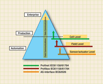
Over the past decade Profibus has become the world market leader in Fieldbus technology, providing communications horizontally at the field level, as well as vertically through several hierarchical levels simultaneously. Layered and coordinated industrial communication systems, such as Profibus with lower-level interfacing to AS-Interface and upper level interfacing to Ethernet (over Profinet), offer an ideal preconditions for transparent networking in all areas of the production recommended operating conditions (see Fig. 1 ).

Fig. 1. Communication in automation technology is a layered precommended operating conditions.
Together with other fieldbus systems, Profibus was internationally standardized in IEC 61158 in 1999. Part 2 of this standard (IEC 61158-2) defines several transmission technologies of which RS-485 is the most commonly used one in Profibus. Profibus compliance is application dependent, and several components of the design contribute to overall compliance, including the RS-485 transceiver. To select a transceiver, one must understand the physical layer and how the transceiver is part of that layer.
Choosing a transceiver
Two key characteristics differentiate a Profibus from a standard RS-485 transceiver. The first one is the differential output of the driver, VOD, and applies specifically to Profibus DP applications. The second one is the differential output capacitance which is part of the total station capacitance, thus limiting the maximum signaling rate specified by IEC 61158-2. The test specifications for Profibus DP masters and slaves require that the differential peak-to-peak output voltage, VOD(PP) be greater than 4 V and less than 7 V. Most datasheets do not specify the peak-to-peak value but a minimum, zero-to-peak voltage of VOD = ±2.1 V, which is equivalent to 4.2 VPP.

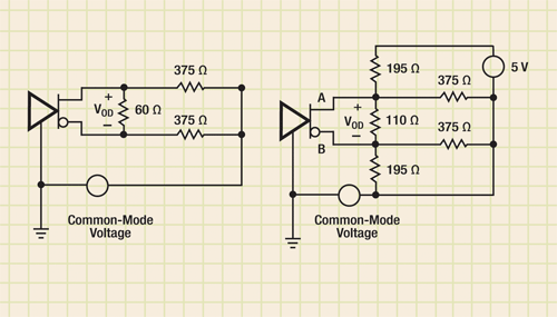
Fig. 2. Two key characteristics differentiate a Profibus from a standard RS-485 transceiver.
While the left equivalent circuit in Fig. 2 represents an RS-485 bus with 32 unit loads, the circuit on the right shows a Profibus network of equal unit loading. The circuit change is due to the additional requirement of the Profibus standard that a pull-up and pull-down resistor must be provided at both ends of the bus in order to maintain a differential voltage in the event of an idle bus.
The 5-V termination voltage creates a positive offset in the VOD, presenting an asymmetrical waveform to the receiver inputs. This asymmetry can cause duty-cycle distortion at the receiver output. The degree to which the duty cycle is distorted depends on the signal rise and fall times and the input thresholds of the receiver. Asymmetry also means that one logic state has less noise margin than the other which is of particular interest since most Profibus applications are in noisy industrial environments. Eventually, the driver must overcome the offset in order to meet the Profibus DP test guidelines, which require that the bus voltages do not differ in amplitude by more than 0.5 V.
The Profibus standard defines Type A cable specifications (Table 100 of IEC 61158-2), which is to be used with 220-Ω bus terminations. Since the characteristic cable impedance can range from 135 to 165 Ω (over a 20-MHz bandwidth, while the equivalent differential termination of a cable end is 171 Ω, reflections due to impedance mismatch in combination with variations in supply voltage can raise VOD to prohibitive levels beyond the Profibus DP test guidelines. To ensure standard compliance, limiting VCC to 5 V and choosing a cable with a characteristic impedance closer to 165 Ω is highly recommended.
The Profibus standards specify the maximum bus capacitance for a given signaling rate, the higher the bus capacitance the lower the signaling rate. For example, at a signaling rate of 500 kbits/s, the total capacitance of all bus nodes cannot exceed 600 pF, while at 12 Mbits/s the maximum allowed capacitance is 200 pF. The bus capacitance includes the differential capacitance of all connectors, stubs, and devices on the bus, but not the cable capacitance. Because changes in bus capacitance are largely due to variations in device capacitances, data sheets of Profibus transceivers ideally should specify the maximum output capacitance in order to allow for accurate predictions of the maximum possible signaling rate. So far the only transceiver guaranteeing a maximum output capacitance of 10 pF is the SN65HVD1176.
Transceiver robustness
Robustness is the degree to which a transceiver can handle electrical overstresses, which can take the form of electrostatic discharge (ESD), voltage transients, and common-mode voltages. The measures of robustness differ by their peak voltages and durations. Low peak voltages and long durations determine the absolute maximum rating. ESD represent high peak voltages and short test pulses. Transient voltages fall in between ESD and AMR ratings.
The absolute maximum rating of the bus pins is the maximum amplitude of a low frequency sine wave that can be applied without causing damage. The recommended operating condition is a subset of the absolute maximum rating. Because most Profibus transceivers are based on RS-485 technology, their recommended operating conditions for bus I/Os are consistent with the RS-485 standard of –7 to +12 V. Absolute maximum rating vary from vendor to vendor, but are generally a 2-V expansion of the voltage range specified in the Recommended operating conditions.
Common-mode voltage range and rejection
Just as the absolute maximum rating bounds the recommended operating condition, the recommended operating conditions bounds the common-mode voltage range of a receiver. A large common-mode voltage range is valuable in applications where drivers and receivers operate at different ground potentials. In this case the ground potential difference adds to the common-mode voltage on the bus and the Profibus transceiver must be able to withstand what is seen as a shift in the common-mode voltage of the receiver input signal. Another robustness indicator is common-mode rejection (CMR). A high CMR (for example, 4 V) indicates a transceiver’s capability of communicating accurately even in the presence of large common-mode voltages varying in magnitude and rise time.
ESD protection
ESD events are typically measured in terms of kV magnitudes and ns rise times. ESD testing is defined in JEDEC standard 22, test method A114-A. This particular standard defines the human body model (HBM). In order to survive these large transients, a transceiver requires internal protection diodes, which quickly react to large voltages.
Transient overvoltage protection
The definition and requirement found in the TIA/EIA-485 standard provides protection for transients that may occur on a line when the high current due to a single contending pair is interrupted. The duration is significantly longer than an ESD event (μs vs ns), and the voltage level is diminished significantly (±25 V vs kV). While the specification calls for test voltages of ±25-V, robust transceivers such as the SN65HVD1176 can withstand transient overvoltages of ±40 V.
Get more information on Profibus at http://electronicproducts-com-develop.go-vip.net/digital.asp
Advertisement
Learn more about Texas Instruments


