Special Purpose Ground-Fault Circuit Interrupter (GFCI),
Class C and Class D
Industrial Shock Block (ISB) is a personnel protection device designed to meet the new requirements for special-purpose GFCIs defined by UL 943C. ISB is the first and only permanently connected Class C and Class D GFCI on the market. Class C GFCIs is introduced to be used on systems where the line-to-line voltage is 480 V or less with a trip level of 20 mA, while Class D GFCI is intended to be used on 600 V systems. These improvements to the standard Class A GFCI (6 mA trip level used on 240 V systems or less) were made to allow the use of GFCIs in industrial facilities.
Equipment Ground-Fault Protective Device (EGFPD)
ISB is also available with adjustable protection settings as an EGFPD. The EGFPD models can be set to trip at 6, 10, 20 or 30 mA. This offers more flexibility since GFCI devices are not allowed to have an adjustable trip level.
Rating and Models
ISB (GFCI & EGFPD) is available for voltage from 208 to 600 V with a maximum full load current of 100 A, and a built-in overcurrent protection supplied by Littelfuse Class T fuses. The load can be 1-phase (line-to-line) or 3-phase, however, cannot have a neutral. The power system can either be solidly-grounded or high-resistance grounded.
Two options for enclosures are available: UL-recognized open-chassis models are available for installation in existing electrical enclosure and UL-listed enclosed models include a NEMA-4X enclosure for stand-alone installations.
Ground Wire (Load-Ground) Monitor
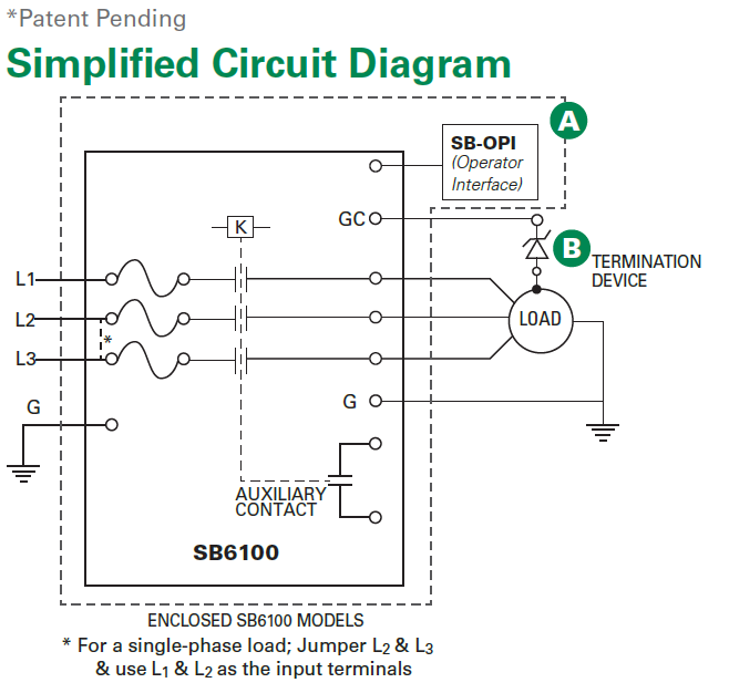
The ISB also monitors the ground wire (load-ground) connection between the ISB and load. This is a required feature for GFCI devices and is optional for EGFPD devices. If the connection is broken, the ISB will provide an alarm by changing the state of the alarm contacts. This monitoring circuit includes an extra wire (pilot wire) between the ISB and load (since the monitoring current is low, only a small wire is required). At the load, the pilot wire is connected to a termination device. The other end of the termination device is connected to the load ground (typically the enclosure)
Download Full Block Diagram Below
Advertisement

Learn more about Littelfuse


