Integrated solutions make analog filter design easy
Selecting the optimal filter configuration as well as using specialized software for filter synthesis
BY JOSEPH SHTARGOT and ALEX DEAN
Maxim Integrated Products
Sunnyvale, CA
http://www.maxim-ic.com
Analog filters play an important part in electronic signal synthesis subsystems, providing functions such as antialiasing and noise filtering for A/D converters (ADCs), as well as “reconstruction” post-filtering for D/A converters (DACs). Different design specifications and requirements dictate the use of the particular filter configurations. The most popular filters include Bessel, Butterworth, and elliptic.
Bessel low-pass filters provide a linear phase response with a ripple-free passband and monotonic roll off. These characteristics make the Bessel filter ideal for time domain applications.
Butterworth low-pass filters have a maximally flat frequency response in the passband with a monotonic rolloff that is much sharper than the Bessel filter. Its phase response varies nonlinearly with frequency. These characteristics present no problems for amplitude-based applications.
And lastly, elliptic low-pass filters have a nearly flat passband response with an extremely sharp rolloff characteristic. The elliptic filter is ideally suited to amplitude-based antialiasing applications.
Design and construction of continuous-time active filters poses substantial design challenges and requires the use of multiple high-performance op amps surrounded with many matched tight-tolerance passive components. Design challenges include selection of the optimal filter configuration as well as using specialized software for filter synthesis. A simpler approach might include the use of highly integrated switched-capacitor filters (SCFs) such circuits can reduce the number of components, make it easier to tune the filter, and trim system power. This article examines a filter implementation, first using a continuous-time filter and then with an SCF approach to show the differences in performance and complexity.
Bessel low-pass filter
Let’s first examine the design of a continuous-time Bessel low-pass filters with a linear phase response, a ripple-free passband and monotonic roll off. These characteristics make the Bessel filter ideal for time-domain applications (no distortion in the oscilloscope/analyzer type measurements). But the cost for the perfect characteristic filter is that the designer needs to construct a higher order (more poles) Bessel filter than Butterworth or elliptic filters to achieve a comparative level of stopband attenuation.
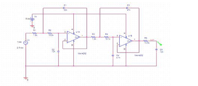
Fig. 1. Two op amps and a handful of passive parts implement a fifth-order, 1.0-kHz, low-pass Bessel filter.
Figure 1 shows a schematic for a fifth-order, 1.0-kHz, and low-pass Bessel filter. This design based on the Sallen-Key architecture and is optimized for minimum component count and uses standard value 1%-tolerance resistors and 5%-tolerance ceramic capacitors. To determine the component values, the design was done using Filter Pro software from Texas Instruments and the design was tested using PSPICE simulation tools.
In many cases, input and output RC filters also require additional op-amp buffers, particularly if signal source impedance relatively high (above few hundreds ohms) and output of the filter connected to the relatively low-impedance circuit (below several hundred kilohms).
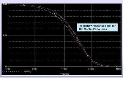
Fig. 2. These frequency response plots show the results of Spice simulations of the five-pole Bessel filter.
Spice simulations run on the Bessel filter circuit are shown in Fig. 2. These frequency response plots are the result of a Monte Carlo run of 100 different “manufacturing builds” for the same filter. The Spice simulator randomly varies the component values within their specified tolerances to account for manufacturing variances. Results of the simulation demonstrate passband variation around
FC = FIN 3±0.6 dB
due to capacitor and resistor value spread in their tolerances range.
To achieve acceptable filter characteristics at 1 to 15-kHz cutoff frequencies (for 80-dB dynamic range or better), designers must use components with even tighter tolerances and better temperature stability. For example:
(a) Amplifiers must exhibit required unity-gain 0.5 to 6.5 MHz for 1 to 15-kHz cutoff frequencies and a THD+N (total harmonic distortion plus noise) factor of better than 0.005%.
(b) Capacitors should be precision ceramic or film capacitors. These capacitors should hold their nominal value over a wide temperature and voltage range.
(c) Resistors should be metal film type with 1% or better tolerances and a low temperature coefficient.
And, to ensure the components deliver the desired characteristics, they should be acquired from reputable sources such as Panasonic, Rohm, Vishay, Kemet, and AVX.
Preliminary estimates shows that component cost of the fifth-order, 1 to 15-kHz cutoff-frequency low-pass Bessel filter could be in the range $1.50 to $2 (each per 1,000). This is not including incremental time expenses for design, test, PCB layout, assembly, components procurement, etc., which are hard to quantify and will vary from company to company. For more detailed information regarding component-variation sensitivity for high-order continuous-time filters see Reference [2].
Maxim and other companies also offer a much more efficient and less complex approach by providing an integrated solution based on switched-capacitor technology, which allows most of filter function to be integrated on a single silicon IC. (For more detailed information regarding SCF operations, see reference [3]). All the designer need do to set up a particular filter characteristic is to use a single inexpensive external capacitor or external clock. The result will be a compact, reliable, predictable, and cost-effective filter design that is less susceptible to temperature and other variations.
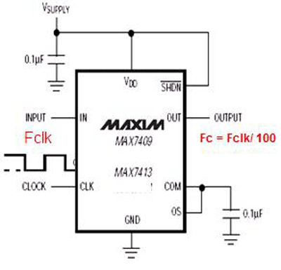
Fig. 3. Setting FC -“cutoff” frequency for a switched-capacitor filter circuit can be done by using an external clock with a 50% ±10% duty cycle.
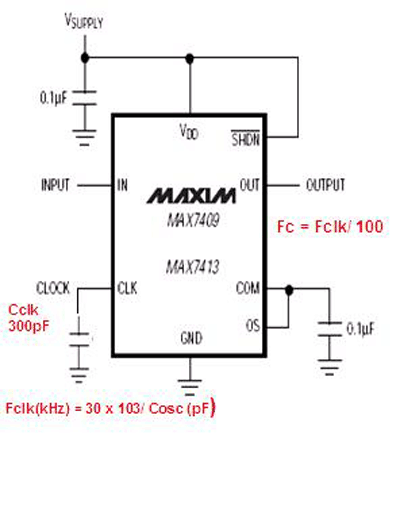
Fig. 4. Setting FC – “cutoff” frequency by using the switched-capacitor filter’s internal oscillator requires connecting the Cclk capacitor between CLK and ground. At Cclk = 300 pF, FC = 1 kHz
Figures 3 and 4 show the simple circuit implementations for fifth-order low-pass Bessel filter based on SCF chips (the MAX7409/7413). Decoupling capacitors 0.1 µF could be generic low-cost ceramic (dielectric type X7R or Z5U), while for Cclk (see Fig. 4 ), a COG (NPO) dielectric type is recommended.
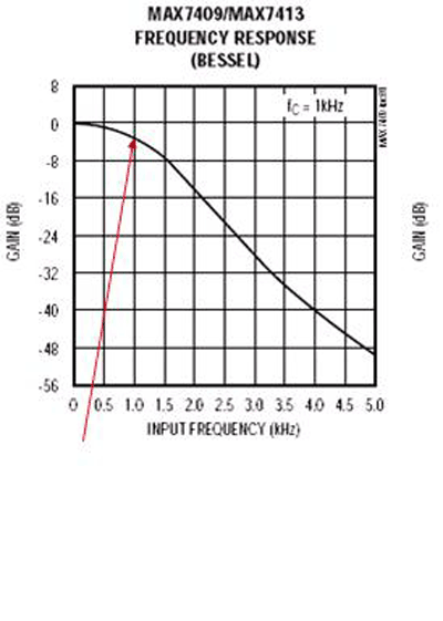
Fig. 5. Passband variation at FC = FIN is only 3 ±0.4 dB over temperature and voltage.
Simulations and tests results shown in Fig. 5 indicate an improvement in passband variation for a MAX7409/7413-based design vs a continuous-time op-amp-based design. Another advantage of these two integrated solutions: easy tunabilty. The cutoff frequencies are clock tunable with two clocking options available: self-clocking or external clocking. In comparison, changing the cutoff frequency in the op-amp-based design often requires fundamental redesign. ■
Additional references
[1] Application Note 3494, “The Basics of Anti-Aliasing: Using Switched-Capacitor Filters” http://www.maxim-ic.com/an3494
[2] Application Note 738, “Minimizing Component-Variation Sensitivity in Single Op Amp Filters” http://www.maxim-ic.com/an738
[3] Application Note 733, “A Filter Primer” http://www.maxim-ic.com/an733
Advertisement
Learn more about Maxim Integrated


