Simplifying sensor monitoring can reduce space and improve energy efficiency
BY CLARK KINNAIRD
Texas Instruments
Dallas, TX
http://www.ti.com
Applications in factory automation, process control, test and measurement, robotics, building automation, and medical markets need to monitor sensor inputs with industrial-sized digital levels. These signal voltages (12-V, 24-V, etc.) are dangerous to the microcontrollers that are processing signals.
Typically, discrete components are used to level-shift, filter, and isolate signals before reaching the controller. As systems become smarter and monitor more sensors, the number of discrete components becomes a limitation in terms of board size, channel density, and power dissipation. To address these concerns, integrated input devices have been introduced to provide a more compact, reliable, and energy-efficient means for taming the industrial input signals.
Reduced hardware/increased intelligence
Simple industrial input designs duplicate level-shifting, thresholding, debounce, and isolation circuitry for each channel. As the number of channels increases, this approach becomes prohibitive.
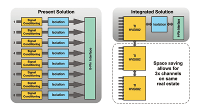
High component counts mean higher cost, increased board space, and reduced reliability. New designs can take advantage of the benefits of serial schemes, whereby the input data is converted from separate parallel channels to a single-serial stream.
Once the input data is serialized, only a few microcontroller IO pins are needed for clocking, control and data input. If isolation is used between the field side and controller, serialization also reduces the number of isolator channels (see Fig. 1 ). If many channels are to be sampled at rapid intervals, high-speed isolation technologies such as capacitive isolators provide over 100 Mbits/s for ample throughput.

Fig. 1. Serialization reduces size and part count, and facilitates more channels.
One consideration for using a serial stream is to ensure that all parallel inputs can be latched simultaneously. This avoids any possible discrepancies due to time shift between channels. Industrial serializers are available to provide this latching control where more than 160 channels can be latched into a single serial stream.
Another benefit of serialization is that diagnostic information such as over-temperature, supply monitors or parity bits can be incorporated into the serial stream with no additional I/O needed. This can enable safe shutdown, intelligent debug and system-level diagnostic checks, all of which reduce down-time and enhance system safety.
Reducing system power
Various applications have different on-signal current requirements. Typical values may be based on industry standards, such as the 2-mA minimum set by IEC 61131-2 for 24-V inputs, or LED or optocoupler turn-on requirements (often 10 mA or more).
Designers strive to meet these on-current requirements across all valid input voltages. This can lead to high power dissipation when inputs reach levels of 24 V or even higher.
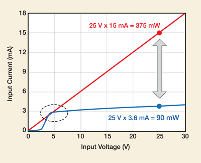
Adding an active current-limit circuit can reduce overall power dissipation significantly (see Fig. 2 ), especially for systems with many channels. This can ease thermal design and enable higher channel density and smaller system sizes.
For example, an industrial sensor may designate an on-state for all signals above 5 V. If an LED is used as an indicator, the on-current should be at least 3 mA for all valid on-voltages.
This leads to an input resistance of approximately 5 V/3 mA = 1.67 kΩ. When the input signal reaches 25 V, the same input resistance leads to a 15-mA current, and over 300 mW of power dissipation.
An active current limit starting at 3 mA for all on-state voltages reduces the power to less than 100 mW, while still providing LED indication of all valid on-states. An active current limit can be implemented with a few transistors and resistors, or designers can use integrated solutions available from various vendors.

Fig. 2. Limiting input current can save significant power.
Glitch/debounce circuits
Spurious transitions such as switch bounce, or “glitches”, are problems in many industrial input signals. These glitches must be cleaned up, and there are several possible implementations.
One approach is to pass all transitions through the input channel and task the system controller with filtering the information. In most systems, it is preferable to “debounce” the signals at the input, before these glitches propagate through the circuitry.
One typical method is to use simple RC circuits to low-pass the incoming signal. A mechanical switch contact may bounce for several milliseconds, with numerous transitions before stabilizing.
An RC filter with a time constant of 5 ms will integrate the signal and smooth the transitions into a single state change. For the example in Figure 1, with 1.67-kΩ resistance, a capacitor value of 3-µF is needed for a 5-ms time constant. Disadvantages of the RC filter are that additional components needed, and that an RC filter can switch states while the input is still oscillating if the signal duty cycle is high enough.
Another method of filtering the inputs is to use a two-stage, retriggerable state machine that latches each transition and is gated by a debounce timer. If the input is stable until the debounce timer elapses, the new output state is set.
If a new transition is detected, the timer is reset, so no glitch signals are transmitted. This state machine is more complex than an RC filter and requires a clock signal, but it won’t change states until the input is stable. It can be implemented with a few gates and flip-flops, or it can be integrated into an input device. ■
Advertisement
Learn more about Texas Instruments


