The capacitor is a seemingly simple device with of two electrode plates separated by a dielectric layer. Capacitors are often named after the material used in their dielectric layer, such as in ceramic or film. They may also be named after one of the electrode plates like aluminum or tantalum. A type known as “polymer capacitors” refers to the cathode plate of a polarized capacitor. The organic conductive polymer, poly-ethylenedioxythiophene (also known as PEDOT), was introduced to capacitors in the late 1990s. It is an exciting alternative to the traditional manganese dioxide (MnO2 ) used in tantalum capacitors.

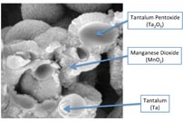
Fig. 1 : SMT tantalum cross section.
Difference between polymer and MnO2 tantalum
The only physical difference between a polymer and MnO2 tantalum capacitor is the cathode material used. Figure 1 shows a cross section of a tantalum chip. The anode “pellet” is the same for either cathode material. This pellet is formed in series of steps. First a group of tantalum particles are sintered together to form a single structure to form the anode electrode plate. Next the pellet is dipped into an electrolyte where a voltage is applied, allowing the dielectric layer of tantalum pentoxide (Ta2 O5 ) to grow.
At this point, either a cathode layer of MnO2 or polymer can be grown over the dielectric structure. Finally, the pellet is attached to a lead frame and covered in epoxy. While this results in capacitors that look the same, the internal structures are different.

Fig. 2: SEM of tantalum-MnO2 .
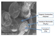
Figure 2 shows a cross section of an actual tantalum- MnO2 pellet. This picture highlights how the hard materials tantalum and manganese dioxide surround the relatively delicate material Ta2 O5 . Figure 3 shows a similar cross section for a polymer-tantalum pellet.

Fig. 3: Cross section of polymer-tantalum pellet.
Polymer advantages
There are significant advantages to using the polymer such as much lower ESR, increased reliability, benign failure modes, reduced voltage de-rating, and lower costs.
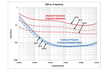
PEDOT is technically classified as a semiconductor; however, it is highly conductive relative to MnO2 . The conductivity for PEDOT is in the range of 100 to 1,000 S/cm, while MnO2 is in the range of 1 to 10 S/cm. For actual components this can mean orders of magnitude lower ESR. Figure 4 illustrates the ESR difference between an MnO2 and polymer tantalum. In this case, the anode pellet is the same; the only difference is the cathode layer.

Fig. 4: An ESR comparison for tantalum and polymer.
Across temperature changes, the polymer cathode exhibits very little change in conductivity (or resistivity) compared to traditional cathode materials. Neither tantalum-MnO2 nor polymer-tantalum capacitors have a wear-out mechanism, as their constructions do not contain an electrolyte. They are a solid-state structure that, based on HAST analysis, would have a nominal lifetime on the order of hundreds or thousands of years. The most appropriate consideration for a polymer-tantalum is their “turn-on” performance when compared to MnO2 . A tantalum capacitor is most likely to fail when voltage is first applied. When a tantalum capacitor goes through a reflow soldering process, the CTE mismatches among the tantalum, Ta2 O5 , and cathode material causes stress on the delicate Ta2 O5 , which damages it to some degree.
Traditional MnO2 causes more damage to the dielectric layer than the conductive polymer. This results in a more robust component when using polymer. Additionally, if a fail-short condition shoroccurs, the polymer will not ignite.
The experiences of tantalum catching fire on failure are actually related to the MnO2 being used as the cathode and not the tantalum or its oxide. When polymer is used as the cathode, there isn't an opportunity for the capacitor to ignite.
When a leakage site in the Ta2 O5 allows enough current to flow, localized heat is generated in the cathode layer. If the temperature is above 400°C, the MnO2 will transition into Mn2 O3 , which is nonconductive. However, this process also creates an unbounded oxygen atom. In situations where current is limited, this process will actually heal or proof the leakage site, making the component more robust. In situations where current is not limited, heat can be generated so quickly that an exothermic reaction begins which is fed by these unbounded oxygen atoms. When you have heat and oxygen, you get fire.
A similar healing process occurs with polymer-tantalum. The unique benefit is that the when the polymer heats up, it oxidizes which breaks down the polymer chains. This also turns the material into a non-conductive state. The advantage of the polymer's healing process is that no free oxygen is left available. Also, since it is significantly more conductive there's less heat, also reducing the ability for ignition.
As mentioned, when these parts go through the reflow oven, weaknesses are formed in dielectric layer. These weaknesses are what cause leakage current to flow through the dielectric layer and also contribute to the “power-on” failure of tantalum capacitors.
The damage caused in MnO2 tends to be more extensive than polymer. For this reason, MnO2 -based tantalums are generally recommended to be used with 50% voltage derating. While polymers equal to or below 10 V only require 10% and polymer rated above 10 V need a 20% derating. Interestingly, even with only 20% voltage derating, polymers still have a lower power-on failure rate than a similar MnO2 with 50% derating.
Polymer trade-offs
There are a few trade-offs to consider when selecting a polymer-tantalum for an application. The conductive polymer has a limit to its operational temperatures. While some polymer capacitors can be rated to 125°C, most are limited to 85°C or 105°C applications. Given the limitation of the material, it is unlikely this upper limit will be increased significantly in the near future.
While polymer based capacitors do have the ability to self-heal, their high conductivity means less localized heating. With less localized heating, there will be less self-healing or proofing from the cathode layer. This results in higher leakage currents. For example an MnO2 design with 1 nA of leakage current may have 1 µA of leakage current when a polymer cathode is used instead.
There are more manufacturing steps when using conductive polymer. This could lead to the conclusion that these capacitors would always be more expensive. Since these capacitors are often used in switching power supplies, the switching frequency should be taken into account.
MnO2 -tantalum versus polymer-tantalum switching example.
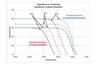
Figure 5 shows the frequency response of an MnO2 and polymer tantalum across different temperatures.

Fig. 5: Capacitance vs frequency for tantalum and polymer tantalum.
At room temperature (25°C), the MnO2 (standard) tantalum starts losing capacitance after about 10 kHz while the polymer tantalum maintains its capacitance past 200 kHz. This is with both capacitors rated for the same voltage, same capacitance, and same case size. However, if multiple standard tantalums were in use, they may be able to be replaced with a single polymer. Even if the per-piece price may be higher, the total solution price could be lower. In addition to voltage, capacitance, and size, production volume plays a role in the price of a capacitor. Each year there are fewer MnO2 tantalums being produced while polymer tantalum production grows. These two combined make cost a potentially neutral trade-off or, sometimes, a cost savings.
Advertisement
Learn more about Kemet Electronics


