BY CRISTIAN FILIP, Product Architect, Board Systems Division
Mentor Graphics, a Siemens business
www.mentor.com
The Joint Electron Device Engineering Council (JEDEC) standards organization has been working on the fourth revision of the JESD204 serial interface specification that was recently approved by the JEDEC Board Ballot JCB-17-43. This standard, published at the beginning of 2018, defines the requirements for a high-speed serial interface connecting analog-to-digital (ADC) and digital-to-analog (DAC) data converters to logic devices like FPGAs and ASICs.
Revision C of the standard increases the maximum data rate from 12.5 Gbps to 32 Gbps and adds support for two additional link layers: 64B/66B and 64B/80B. As for the previous revisions of the specification, the changes were driven by the need for smaller device packages with fewer differential I/Os, lower cost, and reduced interconnect complexity.
In this article, we will review some of the key aspects of the JESD204C standard relating to the channel-compliance methodology.
Physical layer specification
The JESD204C specification is divided into multiple documents, each one of them defining the aspects of various communication layers. The physical layer of the interconnect is described in the JESD204-100 document, which designates six classes of links grouped into two categories. Category B includes B-3, B-6, and B-12, each one of them having a different maximum data rate.
The three category C classes — C-S(hort), C-M(edium) and C-R(eflective) — have the same maximum data rate of 32 Gbps but carry different minimum reference equalization architectures depending on the channel’s insertion loss characteristics. The transmitter, receiver, and channel compliance method for category C classes is based on a variant of the IEEE 802.3 channel operating margin (COM), called JESD channel operating margin (JCOM).
IEEE 802.3 COM
COM is an emerging compliance method for channels operating at high data rates. It was introduced in the IEEE 802.3bj standard and was quickly embraced by newer revisions of the same document and other standardization committees such as OIF-CEI, Fibre Channel, and JEDEC.
The COM computational algorithm is, mathematically, a subset of statistical analysis using single bit pulse responses from s-parameters of the victim and aggressor channels. The algorithm is described in detail in the IEEE Std. 802.3 Annex 93A and involves a number of steps that can be divided into three main groups:
1. Frequency domain (FD) transformations and conversion to time domain (TD)
2. TD signal processing and optimization
3. Final COM calculation
The computational process starts with the channel’s four-port scattering parameters of the victim path and all the significant, non-alien crosstalk aggressors obtained from measurements, electromagnetic simulations, etc. These models are converted to the differential mode and then cascaded with generic package models and single-ended terminations to facilitate the voltage transfer function for the victim and aggressor signal paths.
Next, the transmitter Feed Forward Equalization (FFE) and receiver Continuous Time Linear Equalization (CTLE) are applied by multiplying the non-equalized transfer functions with FFE and CTLE transfer functions.
The equalized transfer functions are converted into a single bit response (SBR) by Inverse Fast Fourier Transform (IFFT). The SBRs are shaped with an optimized combination of Transmit (Tx) and Receive (Rx) equalization based on a “full grid search” of the configuration space denoted by the minimum reference requirements defined in the standard and a signal-to-noise ratio (SNR) optimization figure of merit (FOM). Noise and jitter are included in the calculation by convoluting their amplitude distribution obtained from inter-symbol interference (ISI) and crosstalk.
The final result is a die-to-die FOM, defined as the decibel ratio of signal amplitude peak interference to statistical noise amplitude expressed in decibels:
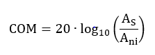 Here, AS is the amplitude of the signal, and Ani is the peak-to-peak amplitude of the noise at the sampling point for a given target detector error ratio denoted by DER0 . A channel is considered to be compliant if the computed COM value is larger than a specific threshold value, which typically is in the 2-dB to 3-dB range. This threshold value was included to account for various impairments that are not accounted for in the COM algorithm.
An optional forward error correction (FEC) block can be included in the receive path to identify and correct some bit errors. Channels that include FEC have a less stringent requirement for DER0 (Fig. 1 ).
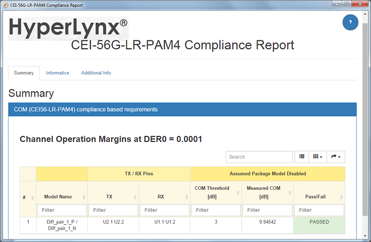
Fig. 1: Example of an IEEE COM analysis report.
Compared to full statistical simulators, COM was built on several assumptions that were needed to simplify the algorithm and improve its performance. Some areas affected by those simplifications are the computations of the contributions from the input jitter and crosstalk. Moreover, COM considers only two package variations based on two long and short transmission line models.
It also constrains the fixed FFE architecture to two or three variable tap coefficients and the CTLE implementation to two or three poles and one or two zeros. Some of those limitations are being addressed by JCOM that allow for custom device package and transceiver models to be used jointly with the COM algorithm.
JESD COM
In JCOM, the Tx and Rx models are decoupled from the computational algorithm, and the standard describes a mandatory interface to be used by the model developers to communicate with the algorithm. Furthermore, a number of improvements compared to the IEEE 802.3 COM have been incorporated in the transceiver and package models. Among them, the output/input impedances of the transceivers are modeled as frequency dependent return loss as opposed to a constant resistance.
Also, model makers have complete freedom in regards to package scattering parameters to be used in the simulations. The FFE, CTLE, and Decision Feedback Equalization (DFE) are encapsulated in the device models and can report the number of available settings (Fig. 2 ).
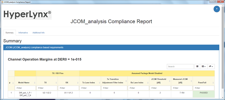
Fig. 2: Example of a JCOM analysis report.
A new concept in JCOM relates to lanes that include characteristics of the device such as rise/fall time filters, terminations, and packages. The computational algorithm is similar to the one from IEEE 802.3 COM, but the equalization optimization is performed for each possible combination of transmitter/receiver lanes and transmitter rise/fall times. JCOM is calculated as the minimum value resulting from all of those combinations, and it is compared to a 2-dB threshold for channel compliance checking.
Conclusion
Despite the simplifications in the COM and JCOM algorithms, those compliance methods offer several advantages when compared to frequency domain-based metrics and IBIS-AMI simulations:
- Favor the tradeoff between loss, reflections, crosstalk, and device specifications
- Allow for solution space exploration early in the design cycle even if device-specific models are not available
- Eliminate all the complexities associated with IBIS-AMI simulations that can be intimidating for many users
- COM/JCOM simulations are faster, making them more suitable for the post-layout screening phase of large designs
- Can efficiently be used to predict performance across high-volume manufacturing (HVM) tolerances with the Polynomial Chaos Expansion (PCE) method and design of experiments (DOE) studies
For the JESD204C standard to be adopted, it needs to fulfill the needs and requirements of all the stakeholders that include chip and EDA vendors as well as the end users like the system integrators. While the supplied Tx/Rx reference models can be used for interoperability testing purposes, like COM, JCOM has set the ambitious goal of increasing the accuracy of the simulations compared to COM by adding support for the custom device and package models.
Advertisement
Learn more about Mentor Graphics


