Low-battery detection is important in battery-powered systems to alert the user to replace the battery. In some cases, a secondary level of detection is necessary to alert the system to a critical low battery level. A nanopower voltage detector device can be implemented that combines a low-power reference and a comparator to build a simple low-battery-detection circuit.
Measurement setup
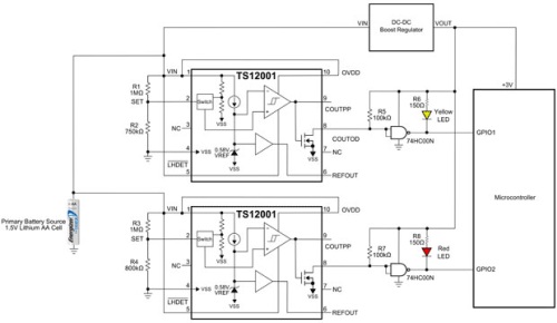
As shown in Fig. 1, a low-battery-detection application circuit can be designed using two low-power voltage detectors, such as the Touchstone TS12001. The detectors are powered by a single 1.5-V lithium AA battery, whereas the other parts of the circuit are powered from 3 V, supplied by a separate boost converter. A threshold voltage of 1.356 and 1.288 V is set for the top voltage detector IC and the bottom voltage detector IC, respectively. When the battery drops below a programmed threshold voltage, the detectors’ open-drain outputs switch from a LOW state to a HIGH state. Detector output voltages are then applied to NAND gates that generate a LOW state to forward-bias the LEDs. The NAND gate outputs are also connected to GPIO inputs of a microcontroller. When the yellow LED detector is triggered, a low-battery level (1.356 V) is indicated. When the red LED detector is triggered, a critical low-battery level (1.288 V) is indicated.

Fig. 1: TS12001 Low-battery-detection circuit.
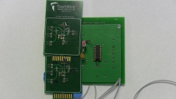
For testing purposes, the 1.5-V lithium AA battery was replaced with a power supply. Figure 2 shows the complete circuit, where two demo boards are used.

Fig. 2: TS12001 low-battery-detection circuit picture.
Results
When the power supply voltage applied to the SET pin reached approximately 1.356 V, the yellow LED turned on and the red LED remained off, representing a low-battery-level condition. However, when the power supply voltage was reduced further and reached approximately 1.288 V, the red LED turned on, indicating a critical low battery level. At this point, both LEDs were on as expected.
Other considerations
Some voltage detectors, like the TS12001, make available a comparator latch function. In this IC, the (“LHDET” ) ¯ pin is useful for capturing one-time events. While this function was not explicitly used in this application, the (“LHDET” ) ¯ pin was connected to VIN, thereby disabling one-time-latch operation.
The open-drain output is useful for voltage level translation. In this circuit, it was used to translate a 1.5-V supply to the 3-V supply environment required by the downstream microcontroller.
Additional information on the TS12001 can be found at http://touchstonesemi.com/products/ts12001, and a video is available here: http://touchstonesemi.com/videos/ts12001-application-video. The application circuit described here achieves a number of goals: (a) user-programmable threshold voltages; (b) low-supply-voltage operation from 0.65 to 2 V; (c) low-monitor-mode supply current of 2 µA; and (d) small active circuit board area of less than 5 mm2 , including external components if the discrete NAND gates are already part of a system gate array.
Advertisement
Learn more about Touchstone Semiconductor


