BY ALEX KARAPETIAN
Director, Sales and Marketing
and THOMAS SKOPAL
Applications Engineer
Acopian Power Supplies, www.acopian.com
One way to fail-safe production lines and manufacturing processes is to use a redundant power supply system. A well-planned system includes not only multiple power supplies, but several redundant ac input power lines as well.
In a redundant arrangement, more than one power supply feeds a single voltage rail. If one power supply fails, the other continues to provide the entire power needs of that rail. Furthermore, a separate feed to each power supply input helps stem failure on the primary side.
Redundant power systems come with various features. Some are complete turnkey assemblies (see Fig. 1 ) that include over/undervoltage, surge protection, isolation diodes, alarms and remote voltage sensing. Others are more basic, consisting of just power supplies and mounting frames. However, most power supplies cannot simply be connected in parallel, so for these systems users must add isolation diodes and perhaps special features required by the particular installation.
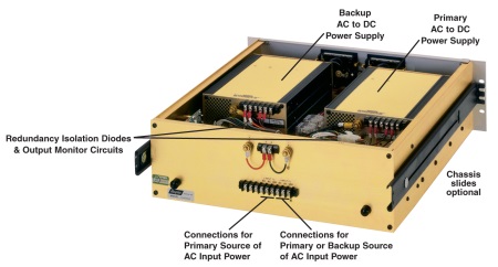
Fig. 1: Turnkey redundant power systems include over/undervoltage, surge protection, isolation diodes, alarms and remote voltage sensing
There are two types of redundant methodologies: primary/backup (100% redundancy) and single-wire current sharing. In a primary/backup configuration (see Fig. 2 ), you are connecting the outputs of two identical power supplies to a common point through isolation diodes is the prevalent way of providing redundant dc voltage. The output of a primary supply is set higher than that of the backup supply, ensuring the backup power supply’s isolation diode is back-biased. Only the primary supply delivers current to the load. However, if the primary supply voltage drops below the backup voltage, the situation reverses and only the backup delivers load current. In either case, the load voltage is not interrupted during switchover.
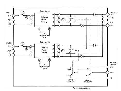
Fig. 2: The primary/backup configuration connects the outputs of two identical power supplies to a common point, through isolation diodes
In this configuration, both power supplies can be set to the same voltage. But, as a practical matter, they cannot remain precisely balanced over long periods. Even a difference of only a few millivolts in output voltages (due to changes in operating temperature, load current, aging of components, and so forth) can switch the load from one power supply to the other and back again.
A single wire current share configuration allows like units to be wired in parallel and each unit shares the load within ±5%. The term ‘100% redundancy’ refers to systems where a backup supply provides all the required operating load current. Another approach is (n+1) redundancy, where n is the number of current-sharing power supplies connected in parallel to obtain the required output current, plus an additional supply having the same current rating as the others to ensure full output current in the event one backup fails.
An advantage of the (n+1) approach is that one fractional backup unit costs less than a supply that provides full output current. Further, in this function, the units run cooler because both power supplies are sharing the load current, therefore increasing life expectancy and reliability.
In either configuration, isolation diodes are incorporated. Isolation diodes typically have a voltage drop of 0.7 Vdc, accompanied by additional drops in wiring, connectors, ammeter shunts, and so on. Consequently, the power supplies must deliver at least a volt more than the specified output voltage of the system. Remote voltage-sensing leads should also contain isolation diodes to prevent a fault in the sense circuitry of one power supply from affecting the other supply.
All power supplies should have overvoltage protection. Shunt circuits, called crowbars in linear units, short circuit the output terminals if the voltage goes too high. Although diodes isolate a supply with decreasing output voltage, they do not block voltages that are high enough to damage loads.
If the utility power fails, a battery backup source (commonly referred to as an uninterruptible power system, or UPS) can pick up the load for a limited time. It supports the load only while its battery pack remains charged. However, the UPS may keep a system running until a downed power line is repaired or the system is shutdown in an orderly way.
If two utility power sources are available, use one for each of the redundant power supplies. Two totally independent power sources provide the highest input redundancy, but even two inputs from the same power source are better than one if they come through different transmission lines and transformers.
A UPS can be connected to one power supply source. With this arrangement, the failure of an input power source, the UPS, or a power supply will not disturb the dc power to the load. Such redundancy required that each input power source supply the entire load current.
For servicing a live redundant power system, a number of special features should be included. For safety, each power supply should have a separate input power switch, and all connections should be made with insulated connectors. Each power supply should also be easy to remove from its mounting, preferably without using tools.
Advertisement
Learn more about Acopian Power Supplies


