Keeping your system's electronics cool is a major design concern with many ac-line-operated products. The internal ac/dc supply is a source of heat that must be removed, to keep the supply (and total package) temperature below its specified maximum. Above that value, you risk shortening the supply's life in proportion to halving the MTBF for every 10°C rise in temperature, and could even induce immediate supply failure. Similar concerns apply to the rest of the electronics as well.
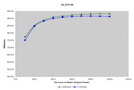
Fig. 1: Power-supply efficiency varies with load. Most ac/dc supplies have their peak efficiency zone close to their maximum load rating (here, the N2Power XL375)
But before you blame the supply for your system's potential temperature rise, step back and look at the numbers. Today's switching ac/dc supplies are fairly efficient, typically in the 80 to 93% range when operating close to their rated load maximum (see Fig. 1 ). This is in sharp contrast to linear supplies, which are only 60 to 70% efficient.
Thus, a 300-W supply is only dissipating between 30 and 60 W, while the remainder of your system is dissipating a much larger portion (in Fig. 1, 240 to 270 W). Often, the main processor alone is a heat source comparable to the supply itself. You'll need to keep this in mind as you make a plan to get rid of the supply's heat.
Basic principals of thermal physics
When you look at the options for cooling your supply and system, basic principles of thermal physics apply. There are three questions to keep in mind throughout planning process:
• How much heat do you have to get rid of?
• Where is the heat going? (Where is the “away” to which you hope to have the heat flow? Getting rid of it “here” may make it a problem “over there”.)
• How is it going to get there?
There are three ways by which heat can flow from a source such as a power supply:
Radiation , as infrared energy. This is the same mechanism by which an incandescent bulb gets rid of the 90% of the electrical energy it does not convert into light. (Although LEDs are much more efficient they do not radiate heat, which actually makes keeping them cool a major problem).
Conduction : heat flow though a solid material, and to another material with which it is in contact
Convection : heat carried away by the flow of a gas (usually air). Note that since there is no opportunity for convection in a vacuum, designers of spacecraft have a much harder time dissipating heat.
For power supplies and many electronic components, radiation from their surfaces are usually a negligible heat-flow mechanism. The bulk of the heat is removed by convection, sometimes with conduction helping move the heat to a location where better convection is available.
Another basic: In the absence of an active forcing mechanism, heat flows from a warmer area or material to a cooler one. Second, the greater the difference between these two locations or materials, the larger the heat flow can be.
Starting your analysis
There's no need to resort to modeling, simulation, and analysis software for the initial assessment of the heat-removal challenge; that can come later. Start with a basic number: how many watts will the supply be dissipating? Look at the supply’s efficiency versus load curve to determine the worst-case loss.
Then look at the total supply capacity, since that's the maximum heat load you have to expect (assuming no other sources of power entering the enclosure, such as a motor which is powered separately). If the ac/dc supply and electronics are in the same cabinet, you have one dissipation scenario; if they are in disjoint locations, you have a different situation, although there will be some linkage.
Since most of the heat removal from the supply and product is by convection, you need a defined airflow path. Heat rises, so the natural, passive airflow will be “up.” Will your system always be in one orientation? What's the orientation of the supply itself, in the package? Where are the intake and exhaust ports for the airflow? If your airflow path is horizontal, unforced convection will be negligible and warmed air will simply stagnate above the supply and electronics (see Fig. 2 ).
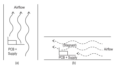
Fig. 2: Convection cooling effectiveness is a function of airflow; a) a vertical cooling path is viable while b) the horizontal path results in stagnant air, near-zero convection cooling effect
Some basic calculations will show if passive convection is even close to sufficient. If not, you'll need to employ forced airflow with fans, and determine the approximate airflow velocity and volume needed.
Fans and active cooling (forced air flow) have clear pros and cons. On one side, they can enable much greater airflow and control over the air-flow path. As a result, the system can dissipate more than it could with just unforced convection cooling, and can be in a smaller package.
But there are downsides to fans: they add bill-of-materials cost, they take up space, they are noisy, they consume power (although smart fan management based on sensing the temperature of the airflow can minimize this) and they eventually fail. The general product trend is to use more-efficient supplies and electronics, and try to avoid the use of fans if possible—but it is often not possible to meet all the conflicting design requirements with a fan-free design and only passive convection.
Once you have the basics of your cooling situation, you need to look at your implementation details. This requires consideration of both overall dissipation as well as how localized these sources of heat are: 100-W evenly spread across a large PC board and supply is not the same as a few concentrated 25- to 30-W sources.
Conventional wisdom is to have the air flow first pass over the cooler parts of the system, then over the hotter parts. This doesn't automatically mean starting the airflow over the power supply. Depending on the specific numbers and the internal layout, the supply may actually be cooler than a main PC board with its few hot ICs in proximity to each other.
There are also contrary cases where it may be better to have the airflow go over the larger heat source first. For example, in a vertical chassis using only passive airflow, and with air coming from the bottom and exiting at the top, the “chimney effect” and resultant convection airflow velocity may be higher if the warmer sources are at the bottom. If they are at the top instead, there may be a smaller temperature differential between top and bottom after the air has passed over the first heat source—and thus, less convection air flow (see Fig. 3 ).
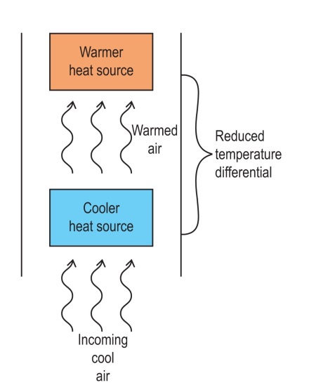
Fig. 3: A reverse-chimney effect occurs when the air flow passes the relatively cooler heat source before it reaches the warmer, and thus the airflow is attenuated by the reduced temperature differential between airflow start and end points
You'll also need a de-rating factor if you have an airflow path which is not straight, or may have partial blockages due to dust buildup on the filter (or even users putting obstructions such as lunch by the intake or exit; you can tell them not to , but they still do it).
In some cases, even if overall flow is sufficient, you may need to use heat sinks on some ICs, or add heat-transfer components (heat pipes and cold plates), just to conduct the heat away from hot spots which have poor localized air-flow access. For example, an EMI/RFI shield placed around an RF power transistor may be good for noise attenuation, but bad for air flow.
Finally, you have to look at the incoming air itself. Air velocity is critical: if the air temperature increases and the air flow remains constant, the component temperature will increase proportionally, up to a limit which is a function of the physical situation and heat sink. This is especially important with convection cooling. Humid air, of course, has greater heat-carrying capacity than dry air. (see Fig. 4 ).
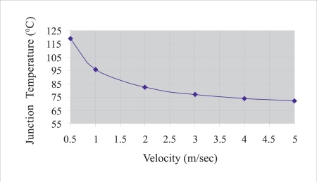
Fig. 4: Velocity of air flow has a significant impact on convection cooling effectiveness; here, the resultant junction temperature for a specific heat sink is shown versus airflow
What about modeling?
All of these variables factor into your cooling strategy and affect the final design. Once you have rough calculations based on thermal principles, it’s often necessary to go to a standard thermal simulation, modeling, and analysis application. You use this to build a virtual model of your proposed design and see what the actual thermal situation will be for environment, air temperature and humidity, and other factors. (see Fig. 5 ).
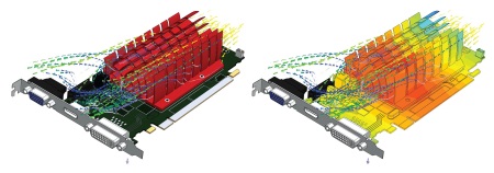
Fig. 5: Thermal-analysis software packages can enable detailed modeling, simulation, and detailed analysis of complex heat sources and cooling paths and techniques (Flotherm/Mentor Graphics)
You may find you need to increase airflow, change the airflow path, use lower-power electronics, or employ some combination of these and other options to ensure performance over the anticipated conditions. You may also need to build some physical mockups to get some critical temperature readings for input data points.
Thermal situation is not a fixed, static analysis, but conditions do change relatively slowly. A system which is operating at its maximum dissipation for only a fraction of the time, but otherwise at lower dissipation, can often be satisfied with less overall cooling capacity. Simulation and modeling will help decide if you really need to design for worst-case thermal dissipation. It depends on the maximum-to-average dissipation span, the duty cycle, and the thermal mass of the system, among other factors.
Getting an initial sense of your cooling situation challenge–and how much work you'll need to do to keep the supply (and electronics) within limits–is not difficult. Ensuring a reliable design requires more sophisticated tools to provide a comprehensive analysis of your approach. The dual pressures of increasing dissipation and shrinking packages for many of today's ac-powered products can make the final design a complex challenge.
Advertisement
Learn more about N2Power


