Look at system power, LED string-array topologies, and current-sink control to get the best system trade offs
BY KEVIN D’ANGELO and DAVID BROWN
Advanced Analogic Technologies (AnalogicTech), Santa Clara, CA
http://www.analogictech.com
The application of LEDs to the backlighting of large LCD panels poses unique power management considerations. The inherent configuration of the LEDs behind the panel, known as direct, or around the panel perimeter, known as edge, and the complexity of the dynamic or static control of LED brightness are major factors. Panels with a direct configuration generally run less current through many shorter LED strings than panels with an edge configuration, which generally run greater current through fewer, but longer, LED strings. Complicating the configuration is the requirement of adhering to the limited power dissipation available in cost-effective power IC packages dominated by the voltage across and the current through the controlling current sources. The LEDs themselves present design tradeoffs with their inherent statistical distributions of color and forward voltage that factor in determining the optimal series/parallel combination of LEDs. Though daunting, it is possible to navigate these constraints and design effective solutions for backlighting large panel LCD displays.
Direct backlighting
The majority of first generation LCD TV displays utilize direct LED backlighting in which arrays of LEDs are arranged in a matrix of tiles behind the LCD panel to directly illuminate the display. This offers power savings, reliability improvements and allows local dimming of individual LED array tiles when compared to CCFL backlight systems. Additionally, varied LED tile brightness in coloration to the LCD image greatly improves the LCD contrast ratio and power savings are gained by limiting higher LED drive current levels to only those tiles requiring a maximum brightness. The tradeoff for individual LED array tile dimming is the added requirement of a high speed data bus and more complex programming that is synchronized to the displayed LCD image which is updated at rates of 120 to 240 Hz. Typical direct backlight systems use as many as 64 to 128 LED channels to form the matrix array. Each LED channel typically consists of 8 to 12 series LEDs that are driven with 50 to 100 mA of forward current. Another consideration for direct backlight LCD displays is they are inherently larger in the form of increased panel thickness over other technologies because the LED arrays must be spaced a distance back from the actual LCD panel in order to properly diffuse the point sources of light from the LEDs.
Edge backlighting
An alternative backlighting system uses LEDs to illuminate the display from the edges of the panel. Backlighting for edge panels requires fewer LED strings/channels, but has a greater number of LEDs per string and must be driven with a higher-voltage power supply. Edge backlighting systems offer less complex system control and require fewer LED strings and fewer LED current sink drivers. Additionally, LED backlight strings are arranged in long light bars along the edges of the LCD panel so the display can be made ultra thin. The control for most LED edge backlight systems requires a simple PWM dimming signal that is already present in most existing CCFL backlight display panels; edge lighting LED backlight systems (see Fig. 1 ) offer a very simple upgrade that is a low-cost drop-in replacement for older CCFL backlight designs. The disadvantage to edge backlighting large LCD display panels is that it does not offer the contrast ratio improvements that direct backlight provides, relative to CCFL backlit systems.
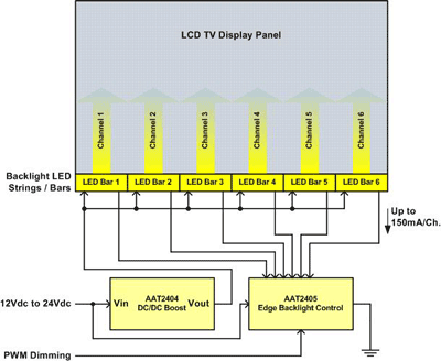
Fig. 1. Typical low-cost LED edge backlight system.
Power dissipation considerations
The power dissipated in ICs driving the LEDs is a limiting factor in designing an LED backlight system. Some ICs have wholly integrated current sinks while others rely on external linearly controlled MOSFETS or a combination of the two to regulate the LED current. In any configuration, the power dissipated in the ICs or MOSFETs will require budgeting.
Controller ICs generally contain a regulating circuit to servo the current sink voltage to a minimal voltage by providing a control signal to the dc/dc converter that supplies the LED power rail. When driving several strings of LEDs on a given IC, the forward voltages of the LED array will create mismatches in the voltages across the current sinks. This is due to the normal statistical distribution of the LED forward voltage in the manufacturing process. A typical manufacturing process may have a standard deviation of 200 mV. The forward voltage standard deviation of n LEDs in a series is given by
σ1 = σ1 x √n
where σ1 is the standard deviation of the forward voltage of a single LED.
For example, a string of n=16 LEDs with a 200-mV standard deviation will have a standard deviation of 800 mV. In context, this relationship determines how to choose n. For the voltages across the current sinks, this implies a worst case scenario for power dissipation. In a control IC of m current sinks, the worst case condition consists of a single LED string at the 3-sigma (3-σ) maximum forward voltage (see Figs. 2 and 3 ) and all other, m-1, strings at the statistical average forward voltage. With the dc/dc converter regulating the current sink voltage attached to the LED string with the 3-σ maximum forward voltage, the m-1 other current sinks will see 3-σ higher voltage and dissipate proportionally higher power.
The type of printed circuit board used to mount the controller IC is also of importance. The number of layers, 2 or 4, and the weight of the copper traces are determining factors in the amount of allowable power dissipation. For instance, a TDFN56 package will yield a thermal impedance of 22C/W on a two-layer board, or 14C/W when mounted on the same size four-layer board. At 60C ambient temperature conditions, the two-layer board allows 3-W of power dissipation and the four-layer board allows 4.6 W. The 1.6 W difference can potentially offer greater flexibility in defining the trade off between the maximum number of LEDs possible per string and the maximum number of current sinks possible in a single control IC.
The following charts depict the power dissipated for 4, 6, 8, 10, 12, and 16 current sinks per IC verses the number of LEDs in series. The two- and four-layer board power limits are shown as horizontal dashed lines, and the voltage required to drive the series LEDs is shown in blue. For instance, at 100-mA continuous current per channel, a two-layer board will allow 10 channels of 10 series LEDs, while a four-layer board will allow 16 channels of 10 series LEDs.
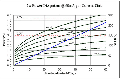
Fig. 2. 3-sigma power dissipation for a 60-mA forward current.
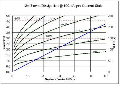
Fig. 3. 3-sigma power dissipation for a 100-mA forward current.
LED string PWM dimming phase control
The latest generations of LED current sink controllers for LCD backlighting can apply a phase delay or delay time to the PWM dimming signal that enables individual current sinks. In direct backlight systems, time delays are sometimes applied to compensate for programming propagation delays across numerous LED channels via the same serial data bus. Most edge systems don’t apply phase delays. However, applying a phase delay evenly across all LED strings will aid in reducing the peak inductor current inherent to the switch mode power supply used to boost the system input voltage to the level required to drive the LED backlight string at a given maximum forward current. For example, in the system shown in Fig. 1 , a single PWM dimming signal could be applied globally across all six LED channels. The applied global PWM dimming signal will operate the system with the same average current, but higher inrush current and peak current through the switch mode boost supply inductor will create un-necessary power losses (see Fig. 4 ). System efficiency can be enhanced by applying an even phase delay of 60C across all six channels. By distributing the turn on time of each LED string channel, the average peak inductor current is reduced, subsequently improving power efficiency (see Fig. 5 ).
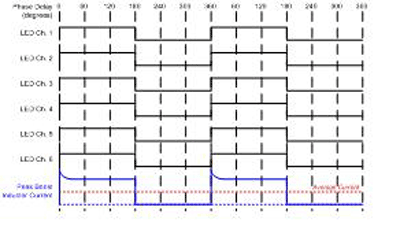
Fig. 4. System with no phase delay.
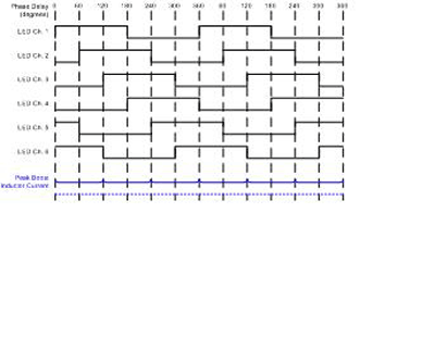
Fig. 5. System with 60 phase delay.
This overview of LCD TV display panel backlighting solutions shows the wide ranges of options and considerations for next-generation LCD TVs. A designer should take into account the multiple considerations that govern system power, LED string array topologies and methods of current sink control to achieve the best system trade offs between power efficiency, system function, and cost. ■
Advertisement
Learn more about Advanced Analogic Technologies


