BY ALLAN LIN, LED Lighting Business Unit Manager, Diodes Inc.,www.diodes.com
(with input from: Henry Nguyen, Senior Applications Engineer, Diodes Inc., Peter Chan, Application Manager, SP Technology and Fred Ebeling, Application Manager, Blue Ridge Lighting Solutions)
It is estimated that a staggering four billion A19 incandescent and MR16 halogen light bulbs are going to be replaced by LED-based equivalents in the years ahead. While high-efficiency, high-reliability LED lamp alternatives are becoming common-place, thanks to rapid evolution in LED driver technology, there remains for legacy installations the thorny issue of effective dimming control.
In this respect, there are still two significant driver compatibility challenges worthy of a recap and more concerted discussion. Firstly, that associated with electronic transformers, the source of the 12 Vac for halogen lamps, and secondly, that associated with the traditional triac dimmer, used to control light intensity via an off-line ac source.
The classic approach
Early MR16 LED lamp drivers consisted of two fundamental components: a simple bridge rectifier to convert 12 Vac to a dc voltage and a large bulk capacitor to store the energy for the output circuit. A simple buck converter then sufficed to drive a few series-connected LEDs.
By only drawing energy from the 12-Vac input when the input voltage is greater than the voltage on the capacitor, high input current peaks occur, reducing the power factor of the lamps. The result is that the number of MR16 LED lamps that can be connected to the transformer is limited as a function of this “surge” current rather than the average current.
A classic solution that addresses this problem with an off-line power supply is to use a power factor correction (PFC) circuit on the front end so that the input current is in phase with the voltage level over the whole ac cycle. Now the “load” to the ac source appears like a resistive load, similar to the original halogen lamp.
Passive PFC
A passive valley-fill PFC circuit on the front-end, composed of a pair of capacitors and “current steering” diodes, provides a ready solution to the peaky current problem. To the input ac, the circuit looks like two parallel capacitors with only half the voltage across them, so the current flows during most of the cycle when the input voltage is larger than that of the capacitor. For the buck converter, the two capacitors appear to be in series, so a higher voltage is available for driving the LED string. Yes, it’s a fine solution electrically, but mechanically problematic. Additional capacitors and diodes simply won’t fit in the space-limited enclosure afforded by an MR16 or A19 lamp.
Active PFC
A better solution in terms of physical size is to use a classic PFC circuit which employs a boost converter to match the current to the incoming ac voltage waveform, thus making it look like a resistive load. This type of circuit uses a constant on-time architecture and requires a very small input capacitor. The circuit draws a current that is in phase with the input voltage and results in a constant input current.
Remember that the main reason for PFC in the LED driver is to reduce the peak surge currents, so that multiple LED based MR16 lamps can remain connected to a single power source. Design challenges remain however:
The most popular power source for the installed base of MR16 lamps is an electronic transformer. In general, a constant load is required for the electronic transformers to function correctly. A cluster of LEDs however typically draws less current than a regular halogen bulb and may fall below the minimum load requirement; causing the electronic transformer to stop working properly, and so cause LED flickering.
Now add to the scenario a triac dimmer, working with the electronic transformer to control the light level. The dimmer controls how much power is delivered to the load by varying the point at which the triac is turned on and off during each half of the mains cycle, and thus controls the power delivered to the load. The main reason for the triac dimmer not working properly is the reduced load of the LED lamp compared to a conventional light bulb.
A further problem is that when the electronic transformer turns on, it creates a very large current surge. Since the triac dimmer is turning on the electronic transformer every cycle, the current surge has to be handled in such a way that it does not destroy the LED driver circuit, electronic transformer, or triac dimmer over time.
Dimmer compatibility
To ensure compatibility with myriad different types of dimmer, LED driver designers have used a bleeder circuit to ensure correct triac function, by allowing current flow while the line voltage is low. This ensures proper firing of the triac since the existing dimmer requires only a few milliamps of current to hold them on throughout the ac line cycle.
Improving triac dimming range
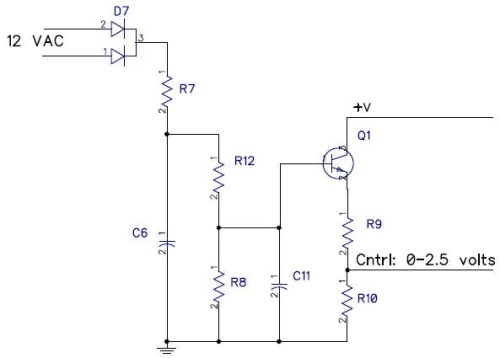
Designers of dimmable LED lamps must ensure that LED lamps are compatible with both forward phase and reverse phase triac dimming circuits (also known as leading edge and trailing edge dimmers). In practice, a triac or electronic dimmer is inserted in series with the line voltage after the ac power supply, which is then connected directly to the input of the LED driver. By adjusting the value of the resistance in the dimming circuitry, different types of dimmers can be configured to achieve a maximum dimming range, from full LED brightness down to the lowest brightness before complete turn off at a predefined cut-off threshold. The Cntrl output of Fig. 1 is used to drive the analog dimming pin of a buck LED driver, such as the AL8807A.
Fig. 1: Triac dimming control circuit.
Performance
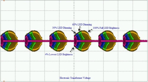
Figure 2 shows the performance of an MR16 lamp that combines the active power factor correction, triac dimming control, and buck LED driver to pull a constant current from the electronic transformer and deliver a constant current to the LEDs.

Fig. 2: Electronic transformer voltage from full to lowest LED brightness.
The electronic transformer’s output voltage envelope is shown for an MR16 lamp consisting of three LEDs at 660 mA at 100% full LED brightness down to 4% lowest LED brightness using an electronic transformer as the power source.
Compatibility with the massive installed base of legacy triac dimmers and electronic transformers remains a key criterion for the design of LED light bulbs. The electronics industry cannot afford it to be something of an afterthought for replacement lamps. The ubiquitous dimmable MR16 and A19 light bulbs present a unique set of design challenges, which, with careful system design and component choice can be met with existing LED driver technology.
Advertisement
Learn more about Diodes Incorporated


