Line input resistors for chargers and supplies
Selecting a line input resistor is not simple, and involves many conflicting factors
BY STEPHEN OXLEY
Senior Applications Engineer
TT electronics
www.ttelectronics.com
Designers of power supplies and battery chargers are faced with many requirements, driven by the need to minimize manufacturing cost while maintaining standards of product safety. A key component in realizing these requirements is the line input resistor.
Selecting a line input resistor is not a simple task, and involves many conflicting factors. On one hand, the resistor must be sufficiently robust to survive repeated in-rush surges and occasional power line transients. On the other hand, the resistor is often relied on for failsafe flameproof fusing in the event of a short-circuit bridge or capacitor failure. And, while safety is always paramount, certain applications come with additional requirements like silent fusing, so that in the event of failure, a consumer is not alarmed.

Functions of the line input resistor
A line input resistor has several potential functions, the relative importance of which varies between applications.
Inrush current limiting
First, a common requirement is to limit the peak value of the inrush current. This is a transient high current, which flows at switch-on of the PSU and is caused by the initial filling of the energy storage capacity in reactive components. In most cases this is due to charging of reservoir capacitors, but in some high-power applications it relates to the magnetization of large transformer cores. The restriction of inrush current protects rectifiers, prevents unwanted fusing or circuit breaker tripping, and avoids pollution of the line supply.
If the maximum permissible value of peak current is known, the required resistance value is simply derived from the line voltage divided by the maximum peak current. The worst case of switch-on at a voltage peak should be considered, and the peak value of line voltage is the figure to use. This gives a minimum ohmic value and this may be raised to give a safety margin, but unless there is a relay shorting the inrush resistor after switch-on, this must be balanced by the need to limit quiescent power loss.
The other critical factor to define is the surge rating required. If the input resistor is wirewound, the manufacturer should be able to give a surge energy rating in joules. This represents the energy capacity of the windings alone, but if the inrush time constant is around 100ms or more, there is time for heat to be conducted into the resistor core, so the effective energy capacity is greater. The inrush energy dissipated in the resistor is independent of ohmic value and simply equals that stored on the charged capacitor of C farads charged to V volts, as given by the formula:
E (joules) = ½ CV2
Note that maximum values of C and V should be used, as the tolerance on both can be wide.
It should be mentioned at this point that an alternative strategy is to use an NTC component, which presents a high initial ohmic value when cold, and then a lower ohmic value when hot. This offers an improved combination of high inrush suppression and low quiescent power loss. However, the design for hot running means it is unsuitable for high-efficiency supplies. Furthermore, a repeat switch-on whilst the NTC is still hot will give little or no inrush limiting.
Transient overvoltage protection
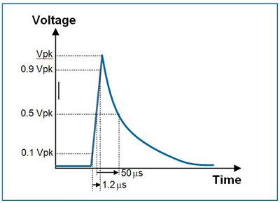
Transient surges on a line input are a common source of product failure and some level of protection against them is normally required. This type of supply line disturbance can, for example, arise when a lightning strike occurs close to power lines and a transient high voltage is induced in the power system. A common standard for simulating the resulting surge is IEC61000-4-5, which describes a 1.2/50-µs pulse (see Fig. 1) . The maximum permissible peak voltage of this pulse across a resistor is limited by pulse energy considerations and increases with resistance value.

Fig. 1: 1.2/50-µs pulse shape.
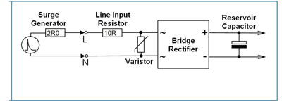
In a typical arrangement the input resistor is followed by a varistor (see Fig. 2 ), which limits the transient voltage to a safe level. The resistor restricts the peak current in the varistor and shares the surge energy with it, thereby lengthening its life. When calculating the peak voltage across the resistor, allowance should be made for the varistor clamping voltage and, for low resistance values, the source impedance of the surge generator.
The first of these is defined on the varistor datasheet, and should be subtracted from the peak voltage appearing at the supply line terminals. The second is normally 2 Ω, and the residual peak voltage is split between this and the resistor in proportion to their ohmic values. For ohmic values above about 40 Ω, the effect of this source impedance is negligible.
For example, with a surge peak of 4 kV and varistor clamping voltage of 700 V, the 10R resistor in Fig. 2 will see
Vpk = (4,000 V 700 V) x 10/12 = 2,750 V (Eq. 1)

Fig. 2: The circuit with the 10R resistor calculated in Equation 1.
Fail-safe fusing
The third function performed by a line input resistor is failsafe fusing in the event of a short-circuit failure of rectifiers or capacitors. In this event, rapid positive opening with line voltage standoff is called for. In some cases, limited overload conditions apply and low-power fusing must be defined.
For certain end markets it is desirable to use a fusible component with UL recognition to UL1412. This makes obtaining UL approval easier and ensures that safety-critical aspects of electrical performance and ongoing consistency of manufacture are independently verified. TT electronics has a range of options in UL File Number E234469.
Case study
When a high-volume manufacturer of consumer appliances faced the challenge of defining the exact fusing mode under wide range of overload conditions they approached TT electronics engineers for a solution. For this, customer safety was paramount, but another key requirement was for low impact, silent fusing. The aim was to avoid consumer concern that could result from visible or audible signs of the failure. In short, if a fault developed, the product should fail gracefully with isolation from line voltage achieved both safely and silently.
In wirewound resistors the core acts as a heatsink for the wire element. This can delay the fusing resulting in the body and coating reaching high temperatures. Depending on the overload power applied, this can result in fragmentation of the coating and ionization of the air close to the point of fusing. If this ionization occurs close to the cap edge and at a voltage peak in the mains cycle, it can initiate a momentary flashover outside the component body. This releases far more energy than is required to fuse the wire element. Although the opening of the circuit is safe for most applications, it may not be silent.
TT electronics engineers addressed this issue in close collaboration with the customer to refine a new coating material and process that delivers silent fusing performance without adversely affecting either safety or cost. The new multilayer coating has a flammability rating of UL94-V0 and shares the same high temperature and insulating properties as standard silicone cement. However, it is more compliant and therefore better able to absorb the thermal and mechanical stresses of an element fusing without fragmenting.
This silent fuse coating is one of a range of options available in the WP-S Series of wirewound resistors covering ratings from 1W to 5W which can be tailored to meet the most demanding of line input resistor applications. It is also used on the ULW Series, which is a UL1412-recognized version.
Top ten design tips
1. Flameproof wirewound resistors are commonly the best choice for line input due to good surge performance coupled with failsafe fusing.
2. Carbon composition technology can be used for extremely high surge energy density, but cannot fuse safely.
3. If multiple wirewound resistors are needed to meet a surge rating, use a series combination rather than parallel. Not only does this share the voltage stress as well as the thermal stress, but also, lower ohmic value wirewound resistors have higher energy capacity.
4. Take great care if using film resistors in this application. Metal oxide, thick film or untrimmed metal film can be appropriate but only for moderate surge requirements. Trimmed metal film types should be avoided.
5. In evaluating the surge and fusing capability of resistors through testing, be aware that there can be batch-to-batch variations. Ideally resistors with specified surge and fusing performance should be used.
6. Flameproof resistors will not ignite. However, under limited overload leading to slow fusing times, the body temperature can become high enough to ignite adjacent materials. If this is a possible fault condition, it is vital that sufficient clearance from plastics and other components be provided. Also PCB standoff by leadforming could be used.
7. Faster fusing under limited overload conditions can be obtained from a wirewound resistor with a glass fibre core instead of a ceramic core.
8. In extreme cases of limited overload fusing requirements a series connected thermal fuse is needed to restrict the body temperature. This can either be discrete or integrated to form a temperature-limited resistor. If discrete, assembly must ensure good thermal contact.
9. It is possible to reduce component count in UL approved designs by using a UL-recognized fusible resistor instead of a resistor with a separate UL recognized fuse.
10. The effect of moderate surges on a wirewound resistor is generally a slight increase in ohmic value due to oxidation. A decrease in value is due to annealing reducing resistivity and is indicative of higher surge stress. Changes exceeding 5% should be avoided. ■
Advertisement
Learn more about TT electronics IRC


