ALAN DAVIS, Manager, Mechanical Engineering
GatesAir
www.gatesair.com
DAVID VRANISH, Applications Engineer
CPC – Colder Products Company
www.cpcworldwide.com
With power densities increasing in electronics applications everywhere, product engineers need better ways to keep critical components within optimum operating temperature ranges. Certainly, heat sinks combined with circulating air continues to be a primary method for cooling installations of large electronic equipment, but there is a growing interest in liquid cooling as a way to more efficiently remove excess heat, improve component longevity and reduce operating costs.
Liquid cooling is especially attractive in applications, such as data centers or radio and TV broadcast facilities, where there are racks upon racks of heat-generating equipment that, if air-cooled, add significantly to the facility’s air-conditioning load. Not only does liquid cooling offer more efficient heat transfer from the heat-producing devices to the cooling medium, it allows removal of the heat from the building without burdening the central air-conditioning system and adding to operating costs. Plus, liquid cooling allows even greater power density to be enclosed in a smaller package, thereby reducing the overall footprint of an application.
Designing a liquid cooling solution for a TV transmitter module or any other type of heat-producing electronic device is a fairly straightforward exercise with one exception: Liquid cooling brings non-dielectric coolants into proximity with electrical components — where any leak, no matter how small, is likely to have dire consequences. As a result, cooling-system designers need to give special consideration to the design and application of tubing, connectors and disconnects in order to protect against the risk of coolant leaks.
Tips for designing liquid cooling systems
Here are several basic suggestions for engineers to keep in mind when developing liquid cooling systems for electronic applications:
- Begin the cooling system analysis at the subassembly level, but also create a simplified system-level model in order to ensure proper flow characteristics at the subassembly level.
- Utilize computational fluid dynamics (CFD) software analysis to pinpoint hotspots in the cold-plate design and identify flow anomalies, such as recirculation flow, eddies and uneven flow through the cooling channels.

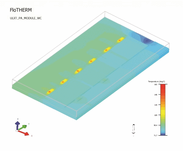
Fig. 1: Computational Fluid Dynamic thermal software helped model the initial cold plate prototype and identify potential hot spots.
- Verify computer modeling through bench testing of the cold-plate design and experimentally determine optimal coolant flow, inlet and outlet temperatures and pressure characteristics. Comparing empirical data to the CFD model results and then correlating the model to the data aids in future analysis, should parameters change.
- Specify the maximum internal diameter possible when sizing fluid connectors to minimize pressure drop across the system.
- Consider serviceability. In modular liquid cooled designs, blind-mate fluid connectors allow for module insertion and extraction without the use of manual valves or tools to increase convenience and minimize replacement time and human intervention.
- Size pumps to the installed system requirements, taking into account the pressure drop (head) of all installation plumbing between the pump, system and heat exchanger, as well as the pressure drop of the heat exchanger itself and other equipment such as filters.
- Size the heat exchanger to system requirements, bearing in mind that some of the heat will be lost to radiation—which may or may not need to be taken into account in the sizing decision.
- Consider using speed-controlled fans in the heat exchanger design so fan speed can be reduced on cooler days to save energy. Speed control should be based on the input temperature of the unit being cooled.
- Work closely with internal resources, such as RF engineers, systems engineers and manufacturing engineers, to save development time, maximize design synergy and ensure manufacturability.
- Take advantage of vendors’ expertise to learn about new technology and get applications assistance.
- Remember that although designs should take worst-case conditions into account, it is not likely that everything will run amok at once. A good Monte Carlo probability simulation will yield more typical results.
A real-world project – cooling UHF broadcast transmitters
To demonstrate the liquid cooling system design process, the following is a step-by-step overview of how GatesAir implemented liquid cooling in its highest-power TV transmitters. The Maxiva ULXT transmitters feature individual power modules that can be built up on a rack, depending on the total power requirement of the transmitter. Each power module has connectors at the rear for power, signal and coolant I/O that need to easily engage connections in the rack when a technician inserts the power module, similar to computer servers in a typical data center configuration.
As an added challenge, each module has to have hot-swap capability so technicians can remove individual modules for maintenance or replacement without affecting the uptime of the transmitter. While hot swapping electronic modules is normally uncomplicated, the addition of liquid cooling connections creates special design challenges that are critical to reliability and uptime.
Each of the Maxiva power modules has a number of heat- producing devices that benefit from liquid cooling. The transmitter’s modules typically contain six FET power transistors, each generating about 250 W of waste heat that needs to be removed. In addition, each power module has a signal combiner that brings in all the RF signals; if the signals don’t precisely match or are out of phase, there is reject power the liquid cooling has to remove. Both the power FETs and the combiner feature cold plates that transfer the heat to the coolant for subsequent removal from the building via the system’s heat exchanger. The design of these cold plates is one of the first steps in the design of the overall cooling system.
Design parameters
The primary cooling design objective is to maintain electronic component temperatures below manufacturer specifications and with sufficient margin to meet the company’s MTBF requirements. The design team’s RF and manufacturing engineers developed these basic design parameters for the power modules:
- 45°C ambient air temperature
- 50°C system inlet coolant temperature
- 50% aqueous ethylene or propylene glycol coolant mixture
- Maximum power dissipation per power amp module:
- 6 FETs @ 250 W = 1,500 W total
- 2 combining reject loads @ 20 W = 40 W total
- Total heat dissipation needed = 1,540 W
- Design coolant flow rate of 1 gpm-per-module
A properly designed cold plate is essential for maximum heat transfer to keep the FET junctions at their optimal operating temperature of 180°C. GatesAir designed its cold plates internally using CFD thermal software to model the initial prototype. CFD software is essential for optimizing the heat transfer under given coolant flow and pressure configurations. It is also critical for identifying potential hot spots in the cold plate due to fluid channel design and placement of the FETs. For example, in a cold plate designed with multiple parallel cooling channels, CFD modeling can help identify any coolant mal-distribution that could lead to uneven temperatures across the cold plate. When the software identifies hot spots, it allows for changes – such as altering channel dimensions or adding internal fins – to help with overall heat dissipation in critical areas.
Over time, GatesAir modified its cold plate design for improved performance. Initially, the company employed an aluminum cold plate with pressed-in copper fittings. While it worked well, its newest design uses a friction stir welded, all-aluminum (T6061) cold plate with multiple cooling channels, resulting in a cold plate design that removes more heat with less coolant flow and pressure. The elimination of dissimilar metals has also reduced the chance of galvanic corrosion in the cooling system.
After modeling with CFD software, the final design met the FET junction temperature target at a coolant flow rate of only 0.6 gpm – slightly more than half of the original estimate. A lower coolant flow rate improved the margin of safety in the system and reduced the load on pumps, heat exchangers, hoses and fittings.
Modeling the cold plate design with CFD software was essential for developing a prototype, but, ultimately, engineers verified the design with bench testing and then final test in a completed power block. This subsequent testing confirmed that all essential parameters were met in the cold plate design.
Other critical components of the cooling system
In addition to the cold plate, another early design consideration was finding a reliable connector for drip-free fluid handling. The cold plates in each Maxiva power module were designed to be plumbed to blind-mating coolant connectors at the back of the module. The application requires coolant couplings to remain connected for long periods of time and then to disconnect without leaking even a drop of fluid. At the same time, the connectors’ internal valves cannot unduly restrict coolant flow.
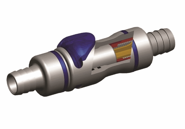
GatesAir worked with connector manufacturer CPC to develop a rack-and-panel version of the supplier’s specially engineered drip-free cooling connector. Each half of the connector incorporates an internal valve that opens upon connection and closes upon disconnection without leaking. Made of aluminum and featuring injection-molded, dripless plastic valves, the design has been proven in over 100 installations of GatesAir transmitter products in the field. Other attributes of the connectors include low insertion force and good flow vs. pressure characteristics of the internal valves – important for optimum coolant flow.
 Fig. 2: CAD model drawing of CPC connectors showing non-spill valve design that use flush face valve technology to provide reliable, drip-free connections and disconnections.
The balance of the cooling system consists of a collection manifold on the back of the power rack, two redundant coolant pumps located within the power block and a remote liquid-air heat exchanger located outside of the building to dissipate the heat. Both the pumps and the heat exchanger are existing designs that continue to meet the criteria for cooling a wide variety of our liquid-cooled transmitters. The heat exchangers come in two sizes, depending on the amount of heat to be dissipated. One heat exchanger will dissipate 20 kW and another will dissipate 50 kW.
End-user results
The Maxiva UHF liquid-cooled transmitters help broadcasters significantly reduce facility air-conditioning loads – and, in turn, operating costs – compared to using heat sinks and air cooling. Liquid cooling also eliminates the noise generated by fans and air movement. Most important for users, the improved liquid cooling design minimizes or eliminates transmitter downtime due to maintenance. Technicians can remove and insert individual power modules while the transmitter is operating because the electrical and cooling line connections are virtually plug and play. The selected module slides into the rack on rails and engages guide-pins that lift the module to line up with both the drip-free fluid connectors and the electrical connectors. Then the module simply pushes in and starts working.
Advertisement


