Here’s how to use interface circuitry and spare microprocessor I/O for low-cost digital control of your applications
BY JOSH MANDELCORN
Texas Instruments
Dallas, TX
http://www.ti.com
Digital power control normally is associated with a specialized complex power controller using a software language different from that used by the system microprocessor. In many applications a system has a microprocessor with unused I/O and memory capability, and power needs with some complexity. In such situations, substantial cost savings can be made by using both a simple power control IC and the existing microprocessor to perform the complex functions. Examples are variable lighting needs for displays and battery charging.
The following discussion outlines low-cost interface circuitry that will allow this microprocessor-based control to occur and design considerations that must be addressed. Specific examples include voltage control approaches and current monitoring and control.
Possible control interfaces include:
Discrete digital outputs (one-bit resolution per output)
Pulse width modulator (PWM) outputs (typically 8- to 12-bit resolution)
D/A outputs (8 bits or more)
Digital potentiometers (typically 8 bits)
The lowest-cost interface is existing spares in the system, or what can be obtained with the lowest-cost upgrade. For example, it may be possible to upgrade the microprocessor to get two additional PWM channels for just $0.25.
Software issues
A software approach assumes availability of software development resources and sufficient program memory on the microprocessor. However, computing time demands for these power management functions are very low because decisions for battery charging, backlighting, and other similar applications need to be made only once every several hundred milliseconds. Since these functions are being implemented on the system computer, a new programming language does not need to be learned.
Resolution issues
Discrete digital outputs are used for low-resolution situations. The simplest one is choosing between two batteries with two current limit levels, or two lighting levels of dim and bright. For applications where a more or less continuous variation is needed, the next step up is 8-bit resolution. This gives increments of 1 part in 256. For a maximum output of 17.5 V, that would be 68 mV per increment.
However, in most applications, the needed variation range is a small percentage of the maximum. Hence, the digital control range should be set to go between this minimum and maximum, giving a much smaller resolution step size. In a battery-charge application, the minimum would be about 12 V. For a 5.5-V variation, step size is 21.5 mV.
If more resolution is needed, going with PWM generally is the lowest-cost approach where increasing to 10, 12, or even 16 bits is achievable with simple software changes. Other approaches require hardware upgrades with added cost such as higher-precision D/A converters.
However, for a given microprocessor clock frequency, increasing bit resolution will result in a much lower PWM frequency, which requires much more filtering to get a clean dc signal. This is because PWM frequency is clock frequency divided by two to the number of bits of resolution.
Voltage-control examples
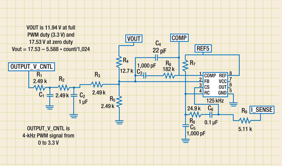
Usually the lowest-cost option with a wide variety of microprocessors is to use PWM outputs. They typically require two stages of filtering (see Fig. 1) .

Fig. 1. PWM outputs typically require two stages of filtering.
Figure 1 is from an actual tested circuit that controls a current-mode flyback where the customer needed output voltage to be higher or lower than input voltage. The PWM signal frequency is 4 kHz. With the values shown, the PWM square wave ripple voltage is attenuated by about a factor of 4,000, or 72 dB.
PWM frequency is generally the microprocessor clock divided by 256 for an 8-bit modulator, or 1,024 for 10 bits. The 4 kHz in the above example is for 10-bit PWM off a 4-MHz clock. If the clock is 40 MHz, then PWM frequency will be 40 kHz, and the capacitors C1 and C2 shown above can be 0.1 µF instead of 1 µF. If only 8 bits are needed, and the clock speed is 4 MHz, the capacitors can be 0.22 µF each.
In the example above, the required adjustable output voltage range needed is from 12.5 to 16.8 V. However, an additional ±4% adjustment range is provided to allow for factory calibration. This allows a low-cost PWM controller to be used such as the UCC2813 with standard ±1% resistors, instead of a more-expensive tighter-tolerance PWM controller with 0.1% resistors. Thin-film 0.1% resistors also are more fragile and less reliable than 1% resistors.
In another application, the customer replaced the PWM with a digital potentiometer. The two-stage filter is removed. Disadvantages of pots are that the control is not linear with the pot setting, and the low-cost pots are all eight bit designs.
Current control and monitoring
Most low-cost power supply controllers do not provide precision current limiting. However, a more accurate current limit can be generated by overriding the voltage error amplifier through an ORing diode.
Because the error amp on board most controllers, such as the UCC2813, has limited pull up current, it is easy for an external op amp to override it. The output current should be sensed in the ground side and amplified with a low-cost ground-sensing operational amplifiers such as the TLC272 or even the LM358, if the input offset voltage is acceptable.
For this control, a single op amp can be used, if current monitoring is not needed. Alternatively, an additional op amp can be used to create a voltage proportional to the load current that the microprocessor can easily monitor.
This can be important in battery charging where the controller needs to know accumulated charge or discharge. Since the lowest-cost op amps come two or four per package, the monitoring function can be provided at very little additional cost.
With the availability of low-cost ground-sensing op amps, current sensing is generally much cheaper if it can be done on the ground side as opposed to the “hot” side. This is unless the power supply PWM controller has hot-side current sensing already built in.
Otherwise, hot-side sensing requires a dedicated level-shift IC or a discrete level shifter that never works quite right due to temperature sensitive offsets.
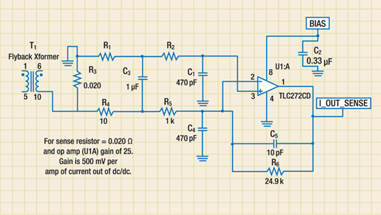
Figure 2 shows an example where a dedicated current monitor IC has been replaced by a low-cost current-monitoring circuit. Even though the current in the transformer output is in the form of pulses, the average current is the same as the load current. The R1 , R4 , C3 filter smooths out the current pulses.

Fig. 2. A low-cost current-monitoring circuit can replace a dedicated current monitor IC.
Amplifier gain is set to target the desired maximum current monitoring range to match the A/D converter range on the microprocessor. In this example, the 500-mV/A op amp output feeding a 3.3-V microprocessor provides a current monitoring range of 6.6 A. Although the example shown here is a flyback, it can and has been applied to other topologies such as single-ended primary inductance converters (SEPIC) and buck regulators.
Examples where this approach can not be used, and high-side monitoring is needed, are external supplies and batteries grounded elsewhere in the system. ■
References
For more detailed information visit:
For more on digital power control, visit http://electronicproducts-com-develop.go-vip.net/linear.asp
Advertisement
Learn more about Texas Instruments


