The input power factor and current THD of an LED lamp are becoming important performance parameters as they provide direct means of comparison between the quality of power drawn by emerging energy-efficient solid-state lighting technology and conventional filament-based incandescent and halogen lamps. From a power transmission and distribution perspective, it is important for the emerging LED-based replacement lamps to maintain high power factor and low-current THD, and reduce the impact of transition from incandescent lamps on power grid infrastructure and network stability. As a result, stringent compliance limits are proposed by various regional regulatory agencies like Energy Star (USA), IEC, and JIS-C 61000-3-2 (Japan). Independent power transmission and distribution companies also may offer higher rebate incentives for increased resistive emulation.
It is well known that a power-factor-corrected (PFC) ac/dc rectifier can be implemented using boost topology with resistor emulation-based, closed-loop feedback control scheme. However, for proper operation, the output voltage of PFC boost ac/dc rectifier is required to be greater than the maximum peak line voltage, typically in the range of 200 to 400 Vdc. However, this is unsuitable for driving low-voltage LED string configurations commonly used in LED lamps. Other PFC rectifier topologies, such as buck-boost or flyback and two-stage cascade supplies using boost followed by buck or flyback converters, result in increased cost and complexity. In theory, a single-stage buck, when configured as a PFC rectifier could provide adequate power factor, low-current THD, and low-output voltage, resulting in the lowest cost and highly efficient LED driver solution. In this article, we examine three primary considerations when approaching a dimmable buck PFC LED driver solution: LED stack voltage selection, the requirements of a single-stage solution, and optimization of dimming performance. We also discuss a unique approach used in designs using a single-stage buck PFC controller optimized for triac-dimming applications.
Consideration 1: LED stack voltage selection
The basis for maintaining a high power factor and low THD is the creation of an input current waveform matching that of the input voltage, as would be seen in a purely resistive load. A resistive load (like an incandescent light bulb) can draw power until the line reaches 0 V. A buck converter driving an LED load can provide power only while the input line is higher than the LED stack voltage. This creates a limitation in the selection of LED stack voltage. However, the limitation does not exclude commonly used, inexpensive LED loads.
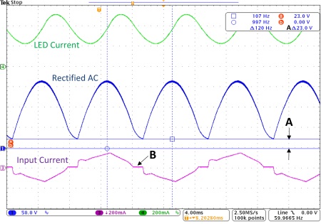
Currently in non-LED load, buck PFC applications, a commonly accepted output voltage that maintains acceptable THD and PFC levels is one that maintains a 50% conduction angle for each line cycle.In practical terms, this equates to 90 Vdc for a 90-Vac minimum input. For LED driver solutions this rule can be followed, if the goal is simply a power factor ≥0.9. If the goal is also THD Fig. 1 , the rectified ac is not pulled lower than the output LED voltage. Here the LED voltage is 23 V as noted by measurement A. A dissymmetry also can be seen in the input current waveform as shown by B on the figure. Extra current is drawn at the start of the cycle to charge capacitances, versus the end of the cycle where the same capacitances are holding up the converter input voltage. However, speaking practically, solutions having a THD

Fig. 1: Buck PFC LED driver waveforms. Conditions: 23.5-V LED stack, 380-mA output current, 14.1% THD .
Consideration 2: A single stage solution
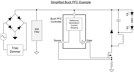
A key point to this discussion is the need for the input current wave shape to match that of the input voltage. This implies a varying power draw over a line cycle. Since our goal is an inexpensive, single-stage solution, the output power also must vary similarly to maintain this relationship. A simplified schematic of such a system is shown in Fig. 2 . This lends itself nicely to LED driver solutions as the output power can be varied over a line cycle with no perceptible change in light intensity to the end user. This allows the simplest control method possible — to vary the output current with the line voltage.
Controlling the output current with the line voltage directly has one disadvantage – line rejection. If the input signal is used directly, changes in input voltage can affect the output control signal and hurt performance. One method is to create a reference that is in phase with, but kept independent from the line. While several options are available, one method stands out to accomplish this goal. Once it is understood that the reference does not have to be sinusoidal to achieve high power factor and low THD, an easily generated triangular reference may be used. In an ideal system employing a synchronized triangular reference, rather than a sinusoidal one, a power factor of 0.99 and THD of 12% can be achieved. Even with distortion from the LED stack drop out is considered, a wide range of LED loads up to 50 V still can be considered, and maintain

Fig. 2: Buck PFC simplified schematic .
Consideration 3: Optimization of dimming performance
Triac dimmers require a minimum current level to maintain each line cycle, or they will not operate consistently, leading to a light output that flashes or flickers. A majority of solutions currently require the LED driver to maintain a high power factor when not being dimmed. If a control system designed to maintain a high power factor is employed while triac dimming is occurring, the output set-point will be controlled to match the input voltage waveform. This can cause a reduction in the output set-point to levels that can result in triac misfire at the start or end of a line cycle.
A solution is to modify the control method, if dimming is being sensed. One method is to change from a high power factor mode to a mode designed to enhance triac compatibility. A simple implementation of this is to modify the output set-point to one that is constant, rather than varying with the line. This also allows a straight forward method to adjust the output demand with the sensed conduction angle of the triac that further enhance the LED driver and contrast ratio performance.
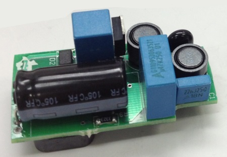
In addition to the challenges discussed here, temperature, cost and size constraints also complicate the LED driver design. One way to simplify the process is to start with a simple, well-known topology: the buck converter. The solution is further simplified knowing safety and regulatory agencies allow the implementation of non-isolated designs in bulbs, if proper mechanical isolation is maintained. Once a few simple guidelines are followed regarding LED load selection and output control, simple, cost-effective and efficient solutions can be easily obtained. The solutions to the issues raised here are fully addressed in the TPS92075 design calculator from TI and have been implemented as explained here. A sample of the demonstration board is shown in Fig. 3 .

Fig. 3: A final implementation of a triac-dimmable buck PFC LED driver.
Advertisement
Learn more about Texas Instruments


