Next generation electronic devices face major technical challenges, which will affect both power management performance and efficiency. Increasingly, conversion and power management applications are requiring current sensors that deliver reliability, durability, and accuracy. These devices, whether they are Hall-effect sensors, transformers, shunt resistors, or anisotropic magneto resistive (AMR) resistors, are necessary for monitoring the power absorbed by the load and controlling and protecting the power supply.
Current sensors must be carefully selected, choosing the most suitable solution for the specific application. According to the type of electrical insulation, current sensors can be divided into two classes: isolated sensors and non-isolated sensors. Non-isolated sensors are suitable for applications with low voltage levels, typically less than 50 VAC or 120 VDC. In case of higher voltages and powers, or when there are floating measurements, it is necessary to use isolated sensors.
One type of isolated sensor can be made using a shunt resistor and an optical or capacitive insulator. An alternative solution is to use a magnetic current sensor. While the first one requires, in addition to the shunt resistor, a certain number of external components, the second is a single-chip solution that requires only an integrated magnetic IC.
Magnetic current sensors
Magnetic current sensors are used in any application where there is a power conversion, including the following:
- Power supplies for datacenter, servers and telecom: The first stage converts the AC mains, single-phase or three-phase, into direct voltage and normally includes a PFC circuit to achieve higher efficiency. The following stages are represented by one or more DC/DC converters that generate the voltages required by the loads (48 V, 12 V, and down to 1 V for the single CPUs).
- Motor drives and inverters: Here, the first stage is an AC/DC converter with PFC, followed by a three-phase DC-AC inverter.
- Uninterruptible power supplies (UPS): The AC/DC converter with PFC is followed by a battery charger, the battery itself, and DC/AC inverter.
- Electric vehicle (EV) motor drive and battery management: The different stages involved in this application are shown in 1. In this case, as further output stages, there are two DC/DC converters and a charger to supply voltage to the 12-V and 48-V batteries.
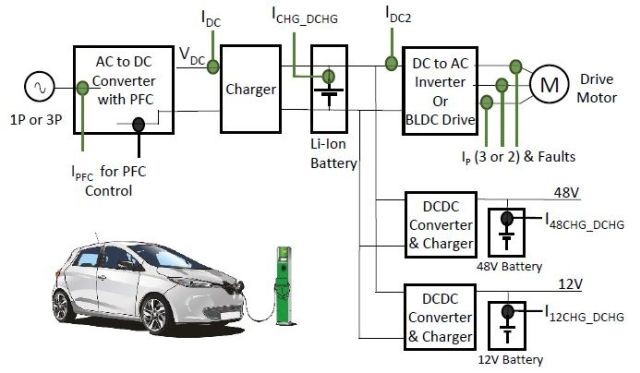
Fig. 1: EV motor driver and battery management system (BMS) application (Image: Aceinna)
All of the above applications require an accurate current measurement at relevant points in the circuit, and therefore, require accurate and reliable sensors. In the Fig. 1 example, the isolated current measurement points are represented with green-colored circles, while the black-colored circles represent non-isolated current measurements.
The magnetic current sensor market is expected to grow from $1.3 billion in 2019 to $2 billion in 2024, driven by applications such as cloud, connectivity, 5G/artificial intelligence, Industry 4.0, EV/electrification, as well as fast silicon carbide (SiC) and gallium nitride (GaN) devices.
Efficiency is a major concern in power supplies. The top efficiency level for the 80 Plus standard, called 80 Plus Titanium, requires efficiencies above 90% for all the fractions of rated load (10%, 20%, 50%, and 100%) and up to 96% at 50% of rated load. Wide bandgap semiconductors (WBG), such as SiC and GaN, will help to achieve those efficiency levels. WBG devices typically feature ~50× faster switching, 3-5× lower resistances, a higher breakdown voltage, 3× better thermal conduction, and a smaller footprint. Power supply will become smaller, more efficient with smoother control, but at the same time will need much higher bandwidth, accuracy, and smaller size current sensors.
Selection criteria
When selecting current sensors, designers should evaluate several key specifications. These include the following:
- Nominal current and overcurrent requirements, current source (AC or DC), and current direction (unidirectional or bidirectional)
- Accuracy over temperature: datasheet shall indicate the total error and the % of reading versus % of full scale
- Bandwidth required to support the switching frequency of power stages
- Output step response, given by the di/dt measurements, which gives an idea of how fast the measurement system needs to be
- Temperature range
- Type of isolation
- Size and cost of the solution
- Electrical and mechanical interfaces
- Other specs include required supply, output type, features (e.g. overcurrent detection), di/dt and dv/dt withstand, UL/IEC certifications, and design simplicity/ease of use
Most isolated current sensors do not support the high switching speeds typical of WBG semiconductors such as SiC and GaN, and those that do support them come at a high cost. The current trend is to overcome the limited bandwidth and the low response time by creating magnetic sensors with high bandwidth and low phase delay. In this way, significant advantages can be obtained such as bandwidth to cover up to 10× switching frequencies, output step response time of less than 500 ns, higher accuracy over temperature, increased dynamic range, reduced loss at higher frequencies, and smaller size.
One solution: Aceinna MCx1101
Aceinna Inc. offers a new family of current sensors based on AMR technology that enables industry leading combined performance in accuracy, bandwidth, and step response in a cost effective single-chip form factor.
The highly accurate, wide bandwidth AMR-based current sensors are available for a wide range of ADC and microprocessor-based power systems and applications. The MCx1101 devices are fully integrated, bidirectional current sensors that offer much higher DC accuracy and dynamic range compared with alternative solutions.
For example, the ±20-A version has a typical accuracy of ±0.6% and is guaranteed to achieve an accuracy of ±2.0% (max) at 85°C. These new current sensors are housed in an industry standard SOIC-16 package (Fig. 2) with a low impedance (0.9 milliohm) current path and are certified by UL/IEC/EN for isolated applications.
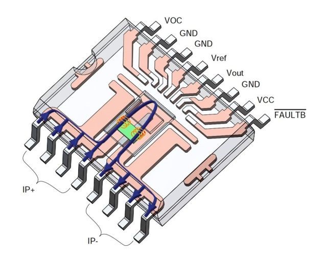
Fig. 2: AMR-based current sensors (Image: Aceinna)
The MCx1101 sensors also guarantee an offset of ±60 mA, or ±0.3% of FSR (max) over temperature, which means that high accuracy can be achieved over a roughly 10:1 range of currents, providing significant improvement in dynamic range compared to leading Hall-sensor-based devices. The devices deliver a unique combination of high accuracy, 1.5-MHz signal bandwidth with industry benchmark phase shift vs. frequency, fast output step response, and 4.8-kV isolation, which make them suitable for current sensing in fast current control loops and protection for high performance power supplies, inverters, and motor control applications.
The article originally published at sister publication Power Electronics News.
Advertisement
Learn more about Aceinna


