Making more accurate high-resistance measurements
Because they are integral to a variety of common test applications, ensuring of high-Ω measurement accuracy can be critical
BY DALE CIGOY
Keithley Instruments
Cleveland, OH
http://www.keithley.com
High-resistance measurements are integral to a variety of test applications, including surface insulation resistance (SIR) testing of printed circuit boards, resistivity measurements of insulating materials and semiconductors, and voltage coefficient testing of high-ohmic-value resistors. Ensuring the accuracy of high-resistance measurements (that is, resistances of 1 GΩ or higher) requires the use of a number of specific techniques, as well as instruments such as electrometers, source-measure units (SMUs), or picoammeter/voltage source combinations.

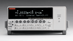
Electrometers such as this Model 6517B can be particularly useful for measuring extremely high resistances.
Constant-voltage method
Measuring high resistances with the constant-voltage method demands an instrument that can measure low currents accurately in combination with a constant DC voltage source. Some electrometers and picoammeters provide a built-in voltage source and can automatically calculate the unknown resistance.
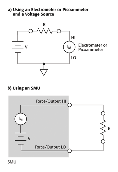
Two basic configurations for the making measurements with the constant-voltage method are using an electrometer or picoammeter (Fig. 1a ), or an SMU (Fig. 1b ). In this method, a constant voltage source (V) is placed in series with the unknown resistor (R) and an ammeter (IM ). Because the voltage drop across the ammeter is negligible, essentially all the test voltage appears across R. The resulting current is measured by the ammeter and the resistance is calculated in accordance with Ohm’s Law (R = V/I).

Fig. 1. Two basic configurations shown above can be used for making measurements with the constant-voltage method.
Given that high resistance is often a function of the applied voltage, the constant-voltage method is generally preferable to the constant-current method. By testing at selected voltages, a resistance-versus-voltage curve can be developed, and the voltage coefficient of resistance can be determined. The constant-voltage method is appropriate for measuring extremely high resistances because of the voltage coefficient effect.
The constant-voltage method requires measuring low current accurately, so error sources related to measuring low currents must be taken into account. These include improperly shielded connections to the ammeter, problems related to the ammeter’s voltage burden and input offset current, and the source resistance of the device under test. External sources of error can include leakage current from cables and fixtures, as well as currents generated by triboelectric or piezoelectric effects.
Constant-current method
Several instrument configurations are appropriate for measuring high resistances with the constant-current method:
• An electrometer’s voltmeter function and a current source. An electrometer’s ohmmeter function alone. An SMU’s voltmeter with high input impedance and low-current source ranges.
Using the electrometer voltmeter with a separate current source or an SMU allows making a four-wire measurement and controlling the amount of current through the sample. The electrometer ohmmeter makes a two-wire resistance measurement at a specific test current, depending on the measurement range.
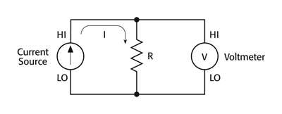
For the constant-current method (see Fig. 2 ), current from the source (I) flows through the unknown resistance (R) and the voltage drop is measured by the electrometer voltmeter (V). This method supports measuring resistances up to about 1012 Ω.

Fig. 2. The constant-current configuration shown above seems straightforward, but users need to be aware of instrument input and output resistances.
Although the basic procedure is relatively straightforward, some precautions are necessary. The input impedance of the voltmeter must be high enough to keep the loading error within acceptable limits. Typically, the input impedance of an electrometer voltmeter is greater than 1014 Ω.
Further, the output resistance of the current source must be much greater than the unknown resistance for the measurement to be linear. The voltage across the sample depends upon the sample resistance, which makes it difficult to account for voltage coefficient when using the constant-current method. If voltage coefficient is a concern, it is better to use the constant-voltage method instead.
Using an SMU
An SMU can measure high resistance in the source current/measure voltage mode by using either a two-wire (local sense) or four-wire (remote sense) method, a technique that eliminates contact and lead resistance, which is especially important when measuring resistivity of semiconductor materials. These measurements usually involve measuring low voltages. The resistance of the metal probe to semiconductor contact can be quite high. When using remote sense, the voltage difference between high force and high sense and between low force and low sense is usually limited to a specified value. Exceeding this voltage difference can produce erratic measurements.
Besides the voltage drop limitation, some SMUs have automatic remote sensing resistors located between the HI Force and HI Sense terminals and between the LO Force and LO Sense terminals. This may further limit the use of a single SMU in remote mode for certain applications, such as semiconductor resistivity. If so, the SMU can be used as a current source in the two-wire mode, and one or more separate voltmeters used to measure the voltage difference.
Using an electrometer
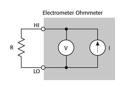
When using an electrometer’s ohmmeter function to measure high resistance (see Fig. 3 ), various factors, including electrostatic interference and leakage currents, can affect measurement accuracy. The ohmmeter uses an internal current source and electrometer voltmeter to make the measurement. It automatically calculates and displays the measured resistance.

Fig. 3. In the above configuration, an electrometer’s ohmmeter function is used to measure resistance R.
Note that this is a two-wire resistance measurement, in contrast with using the electrometer voltmeter and external current source, which can make a four-wire measurement. This is because the current source is internally connected to the voltmeter and cannot be used separately.
Guarding and shielding
The two most common error sources when measuring high resistances are electrostatic interference and leakage current. Shielding the high-impedance circuitry can help minimize the effects of electrostatic interference (shield is connected to circuit LO); guarding offers a very effective way to reduce leakage currents and improve measurement accuracy.
A guard is a low-impedance point in the circuit that’s at nearly the same potential as the high-impedance lead being guarded.
Circuit settling time
The measurement circuit’s settling time is particularly important when measuring high resistances. The settling time is affected by the shunt capacitance, which is due to the connecting cable, test fixturing, and the DUT. The shunt capacitance (CSHUNT ) must be charged to the test voltage by the current (IS ). The time required to charge the capacitor is determined by the RC time constant (one time constant, τ = RS CSHUNT ), so it’s typically necessary to wait four or five time constants to achieve an accurate reading.
When measuring very high resistance values, the settling time can range up to minutes, depending on the amount of shunt capacitance in the test system. To minimize settling times when measuring high resistance values, keep shunt capacitance in the system to an absolute minimum by keeping connecting cables as short as possible. The use of guarding can also decrease settling times substantially.
High-MΩ resistors
Resistors with values of 1 GΩ (109 Ω) or more — often referred to as high-MΩ resistors — come in two types: carbon-film and metal-oxide. Several factors must be considered when measuring them, including voltage and temperature coefficients, the effects of mechanical shock, and contamination. Carbon-film high-MΩ resistors are noisy, unstable, have high-temperature coefficients, display high-voltage coefficients, and are very fragile, when compared with conventional resistors. Metal-oxide types have much lower voltage coefficients (
High-MΩ resistors need extreme care in handling because mechanical shock can alter their resistance by dislodging particles of the conductive material. It’s also important to avoid touching the resistive element or the glass envelope surrounding it; doing so could change resistance by creating new current paths or small electrochemically generated currents. If a resistor acquires surface films from handling or air contaminants, it should be cleaned with a foam-tipped swab and methanol, and dried in low humidity for several hours to let any static charges dissipate. ■
Advertisement
Learn more about Keithley Instruments


