BY KENJI KAWANO and JUN NAKAJIMA
Taiyo Yuden, www.t-yuden.com
Designers building power inductors for today's high-volume mobile markets face a dilemma. On the one hand, the market demands higher-performance systems with additional functionality running at higher current levels. On the other hand, it pressures engineers to squeeze that additional functionality into an ever-smaller package. For the smartphone that is using a quad-core processor running in excess of 2 GHz, designers need inductors for power supply circuits capable of supporting the higher peak operating currents. But at the same time, phone designs are becoming increasingly smaller and thinner. So phone designers also need power inductors small enough to fit within their phone’s shrinking footprint.
The same trends can be seen in tablet design. Today’s customers demand larger, higher-performance screens. But they also expect lighter, thinner tablets. The original Apple iPad tablet, for instance, was 0.5 in. thick. At 0.29 in., the latest iPad Mini is almost half as thick. Accordingly, tablet designers need power inductors capable of supporting ever-higher levels of current, yet small enough to fit into the extremely low profile used by today’s leading products.
Unfortunately, those requirements run counter to traditional principles of power inductor design. Typically power inductors are made of ferrite. Since the saturation flux density of ferrite is not very high, the dc bias characteristics are not very good due to saturation. Designers are turning to compacted metal powder inductors made of high-saturation magnetic flux iron-based metal magnetic particles and an organic binder. In these products, the metal magnetic particles and the coil are formed at the same time. Then the binder is solidified and provides insulation between the metal particles.
New microstructure
A new metal magnetic compacted powder material is able to significantly improve inductor size. The most revolutionary aspect of the new material is that it does not use an organic binder. Figures 1 and 2 below illustrate the unique microstructure of this new material. The powder is comprised of iron (Fe), silicon (Si), and chromium (Cr). The SEM image in Fig. 1 shows the absence of an organic binder in the microgaps between the metal magnetic particles. A transmission electron microscope (TEM) image in Fig. 2 shows the gaps between the particles where a thin oxide layer has formed on the surface of the metal magnetic particles of the metal magnetic powder material.
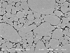
Fig. 1: This SEM image shows the absence (black areas) of an organic binder in new metal magnetic compacted power material.
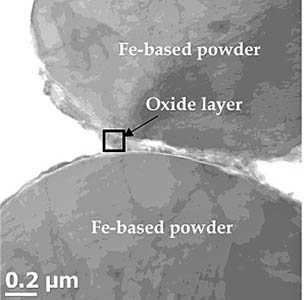
Fig. 2: A TEM image of the new material illustrates the thin oxide layer that forms on the surface of the metal magnetic particles .
Since the composition of the oxide layer is compatible with the metal magnetic particles, it provides excellent insulation characteristics for the metal-magnetic particle surface. Moreover, the oxide layer features high crystallinity — there are no defects in the oxide layer between adjacent metal magnetic particles and the crystals are connected continuously to one another. Given these qualities and the ability to control this layer to between 100 and 200 nm thick, the oxide layer makes it possible to secure the insulation and mechanical strength between metal magnetic particles. This characteristic allows the new material to offer excellent performance characteristics for power coil applications.
Performance advantages over ferrite-based devices
One example of the new metal magnetic powder material is the MCOIL devices from Taiyo Yuden (http://www.t-yuden.com/mcoil/). The devices feature a core with permeability about two times better than traditional composite-type power inductors. The devices also use a hi-µ shielded resin and wound wire on the core. Several important performance advantages have been achieved over conventional ferrite equivalents.
The graphs in Fig. 3 compare the dc bias performance of a metal magnetic powder device with those of the company’s comparable ferrite-based device. With the ferrite device, inductance drops dramatically once dc bias exceeds 2 A, while the MDMK4040 metal magnetic powder device exhibits much higher and more stable saturation current.
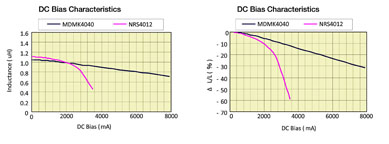
Fig. 3: The inductance of the MCOIL device (black) compared with its ferrite-based equivalent (red) at various levels of dc bias.
By combining the advantages of the metal magnetic material with advances in process technology, the metal magnetic powder products offer space savings over ferrite-type products with a smaller footprint and 40% lower height.
Metal magnetic powder devices also offer significant advantages in terms of RFI shielding. As the graphic below illustrates, the emissions from a metal-based device are far lower than a comparable ferrite-based alternative. This characteristic reduces noise on surrounding circuits, minimizes efficiency loss when the shield case or other components are near the power coil, and minimizes crosstalk with other power coils.
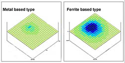
Fig. 4: RF emissions from an MCOIL device compared with equivalent ferrite-based device.
This article was derived from a white paper available for download: www.electronicproducts.com/Passive_Components/Magnetics_Inductors_Transformers/Material_Advances_Enable_New_Generation_of_Power_Inductors.aspx
Advertisement
Learn more about Taiyo Yuden


