Here’s how to increase base station coverage and capacity
BY PATRICK WIERS
Analog Devices, Norwood, MA
www.analog.com
Base station transmitter beamforming and beamsteering are effective methods of increasing base station coverage and capacity. These techniques require multiple transceivers and the baseband processor must compensate for undesired phase offsets of each signal path. Further, this compensation must persist over time. This article describes a method of measuring the phase differences among multiple transmitters at factory test and during operation so that a baseband processor can compensate for these offsets.
Multiple antennas for high performance
Personal communication devices such as smart phones increasingly demand higher data throughput to support new applications.[1] Improving throughput in a given bandwidth and coverage area requires a higher signal to noise ratio (SNR) which implies that the power increases, the noise decreases, or both. Using a higher output power amplifier (PA) is one method of increasing the signal level but it can significantly increase the operational costs of the bases tation and it can result in increased interference with neighboring cells.[2] Decreasing the receiver system noise is also possible but can require heroic efforts to obtain more than a couple dB of improvement over an already-optimized system.
Using multiple signal paths and an antenna array allows the aggregate radiation pattern from the array to have higher gain in the direction of the intended receiver and much lower gain in other directions. Higher transmitter gain in the direction of the intended receiver increases the signal level at the receiver but only increases interference with other receivers that happen to lie within the narrow beam of the transmitter. A narrow, high gain receive pattern directed at the transmitter decreases interference at the receiver from neighboring base stations and mobile devices. Both of these effects improve the SNR at the receiver.
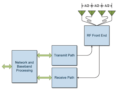
Fig. 1. A four-antenna system.
Figure 1 shows a block diagram of a system architecture in which four antennas share the same signal. The conductors feeding the center antennas are convoluted to emphasize that all antenna cable lengths must be equal.
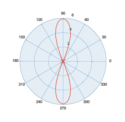
Fig. 2. A four-antenna response relative to single antenna response (dB).
Figure 2 shows a simulated response of this system assuming that the antennas are omnidirectional. The antennas lie on the axis through 180 and 0. The radial axis of the polar plot is gain in dB relative to the gain of a single omnidirectional antenna.
Beamforming and beamsteering
The architecture in Fig. 1 is useful in many current applications but maximizing the benefits of a narrow-beam system requires dynamic beamsteering (moving the main beam), or beamforming (moving the main beam and the nulls). Beamsteering requires the baseband processor (BBP) alter the phase of each antenna signal while beamforming requires the BBP alter the phase and amplitude of each antenna signal.[3] Unless otherwise specified, “beamforming” in this article refers to both beamsteering and beamforming. Figure 3 shows a system that implements beamforming. Here, only the transmit paths are shown for clarity.
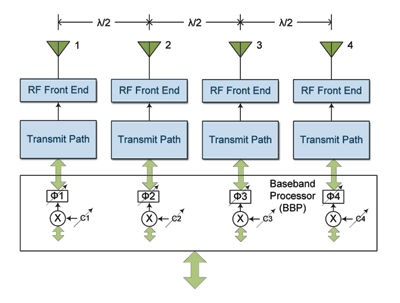
Fig. 3. A four-antenna system with beamsteering/beamforming
Some multiuser protocols such as LTE are designed for beamforming. In LTE, the BBP can adjust the amplitude and phase of resource blocks (RBs) individually, allowing for user-specific beams even during a multiuser subframe[4].
The radiation pattern in Fig. 4 results if the BBP shifts the data for antenna 1 by 0.375λ, antenna 2 by 0.125λ, antenna 4 by 0.125λ, and antenna 4 by 0.375λ. In this beamsteering example, the BBP only applies phase corrections to the data. The figure also shows two lobes moving in concert. In cases where this is not desirable, an array of directional antennas can eliminate the undesired lobe and provide extra gain for the desired lobe.
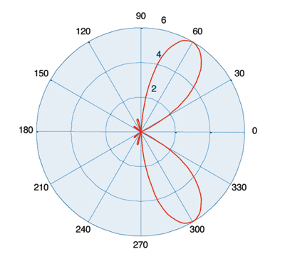
Fig. 4. A steered four-antenna response relative to single antenna response
The plots presented in Figs. 2 and 4 are ideal, assuming that the signals arrive at each antenna exactly as desired. In practice, however, variations result in undesired phase shifts unique to each transmit path. These phase shifts can change each time the system is powered up and they can vary with component temperature changes. This is especially true if the transmitters use different local oscillators or if the path of the local oscillator as it travels to each transmitter block is different.
Undesired phase offsets due to unequal path lengths, temperature drift, and local oscillator (LO) phase differences among the transmitter paths can severely degrade system performance by changing the radiation pattern. For example, if an error of just five degrees is added to each antenna signal (resulting in: antenna 1 = -0.51λ, antenna 2 = -0.17λ, antenna 3 = 0.17λ and antenna 4 = 0.51λ, the result is shown in Fig. 5 .
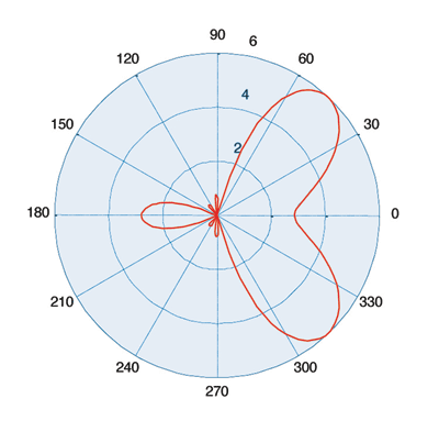
Fig. 5. Steered four-antenna response with undesired phase shifts
Measuring the phase
Clearly, the ability of the system to measure the relative phase offset of each transmitter output is mandatory for beamforming. After calculating the relative phase offsets, the BBP applies a correction factor to each signal path in addition to the phase and amplitude coefficients that will steer the beam.
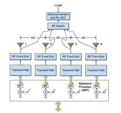
Fig. 6. A four-element beamforming system with Tx path phase detection.
Figure 6 shows a common method for determining the relative phase offsets by using an extra receiver in the system. The curved paths again emphasize that the path lengths from each RF front end to the RF switch must be equal. Downconverting, filtering, and digitizing the transmit signal and then computing the phase as Tan-1 (Q/I) yields phase offsets for each path. The BBP then applies these correction factors to the beamforming coefficients.
The downconversion process requires a fully featured receiver subsystem with the exception that the maximum gain of the receive path does not need to be as high as it does for a normal receiver. Such a solution adds cost but this is outweighed by the beamforming benefits.
Using integration to cut cost
Increasing the level of integration reduces the cost of the implementation of Fig. 6 while maintaining the benefits of beamforming. There are several levels of increasing integration. For example, using a single IC for the entire receiver subsystem or for a transmitter subsystem reduces cost. Further integration such as integrating multiple transmitters and receivers into a single IC yields a solution with the least cost while retaining beamforming functionality.
Combining the receivers and transmitters into the same IC package provides additional benefits for time division duplex (TDD) systems. In that case, the receivers and transmitters are not used at the same time, which allows the receivers to be re-tasked such that they measure the phases of the transmitter outputs during transmit subframes. Such an architecture is shown in Fig. 7 . This figure shows the situation during a transmit subframe. The blocks labeled “Tx Monitor” are the re-tasked receivers that measure the power at the coupler and provide I/Q data outputs during the transmit subframe. For the receive subframe, the receiver circuitry disconnects the Tx Monitor input and operates as a normal receiver.
The first 2 x 2 transceiver uses an internal LO for the transmit and monitor paths. The second 2 x 2 transceiver uses a different LO for its transmit and monitor paths. The frequencies of the LOs are the same but a phase delta may exist and may change each time the transceivers power up.
In Fig. 7, the phase of the output of Tx Monitor 2 will equal ΦAnt1 (the delay from LO 1 in the transmit path to the coupler) plus ΦTxMon2 (the delay of the Tx Monitor path back to LO 1). This is referred to as Φ(det) in the figure. If the two bold traces are matched, then the output of Tx Monitor 3 will be the same Φ(det) plus ΦAnt2 plus ΦLO 2 minus ΦLO 1. Subtracting Φ(det) from this value results in the phase difference between Ant1 and Ant2. The phase differences of the other antenna paths are derived in a similar manner.
Beamforming is a practical method of increasing coverage area while decreasing interference with other cells. Of critical importance in beamforming is the ability of the system to measure the relative phase of each signal near its associated antenna. A receiver subsystem can perform this function but integrated components can reduce the cost significantly while retaining the benefits of beamforming. Components such as the Analog Device AD9356 or AD9357 2 x 2 transceivers reduce cost even further and combine two receivers, two Tx Monitors, and two transmitters on the same die. ■
References
[1] Kapustka, Paul, “4G killer apps: A top five” www.pcworld.idg.com.au/article/345816/4g_killer_apps_top_five
[2] Zhong, Hang Yu and Sabharwal, Ashutosh, “Beamsteering on Mobile Devices: Network Capacity and Client Efficiency,” Technical Report 06-23-2010 , Department of Electrical & Computer Engineering, Rice University, Houston, TX.
[3] Haynes, Toby, “A Primer on Digital Beamforming,” Spectrum Signal Processing , March 26, 1998.
[4] Agilent Application Note, “MIMO in LTE Operation and Measurement—Excerpts on LTE Test,” 5990-4760EN , January 2010.
Advertisement
Learn more about Analog Devices


