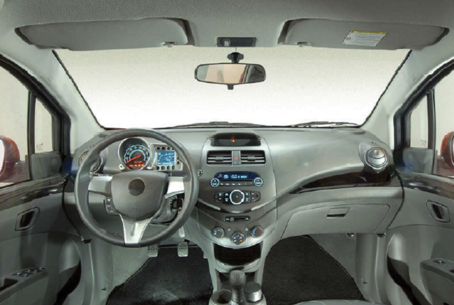
Modern vehicle design is ironic; vehicles strive to be increasingly more energy-efficient while simultaneously producing greater electrical demands. Internet-connected-infotainment systems, safety-related functions, in-cabin conveniences, and other once-luxury items are becoming standard features. As a result, the radio head unit ─ the location housing most electronic subsystems ─ grows crowded, challenging engineers to improve circuit efficiency amid shrinking space and heightened thermal, electrical, and noise conditions.
Challenge #1: Head-unit efficiency
The head unit can host as many as eight to ten major subsystems packed into its compartment, but requires multiple DC-power rails and an efficient way to deal with heat dissipation. It can be said that striking a balance between power demands and constraints is perhaps the head unit’s most glaring challenge. A well-regulated voltage at various currents is required to support processors, memories, displays, and the myriad other components associated with each of the vehicle’s electronic features. Furthermore, the DC/DC regulator must be efficient enough to minimize the inevitable temperature rise resulting from the power subsystems, in order to protect both the electronics and the regulators themselves.
Challenge #2: Taming the car’s electrical and thermal environment
Despite being battery-powered, vehicles do not have a stable and quiet DC source. The nominal 12-VDC battery supply is actually a complex and hostile electrical rail that’s noisy and volatile, further complicating the design of the regulation function. Cold cranking – the battery’s ability to start an engine in cold temperature – can drop the rail to as little as half its normal value. Similarly, the rail can spike when loads are suddenly removed, causing transient spikes as high as 42 V. As a result, regulation circuitry must be able to resist the transients’ effects and continue to function optimally in their presence.

DC power and support are needed for the complex series of circuits that power the onboard display
The fruition of the “start-stop mode” in newer vehicles further challenges electrical systems with repeated load dumps and transients each time the vehicle is stopped and restarted. When activated, the mode shuts off the engine at stop signs, red lights, and in traffic, before restarting them within a fraction of a second to minimize idle gas consumption.
Challenge #3: Electromagnetic interference
A third factor to keep in mind when designing for the harsh auto environment is electromagnetic interference (EMI). Because the vehicle is already susceptible to a pervasive amount of electrical noise from both internal and external sources, every power subsystems must abide by stringent requirements on the maximum amount of EMI it can produce. Similarly, the head unit must remain functional within harsh thermal conditions, operating at temperatures as high as 85°C externally and 105°C internally.
Multiple design solutions
The most common solution for all three challenges adopted by system designers relies on a combination of multiple automotive-compatible linear and switching DC/DC regulators, with one for each DC power rail needed. However, this approach is complex and inefficient, requiring skill in selecting a suitable linear or switching regulator IC for each rail and packing the full set of regulators within the confines of the head unit’s circuit board space.
A significantly more efficient alternative can be found in highly integrated power-management ICs (PMICs), such as Maxim Integrated’s MAX16993 or MAX16930. Unlike solutions assembled from disparate components, integrated ICs create accessibility for system designers working in the auto industry because they exclusively designed for the auto environment and provide multiple DC rails. The MAX16993 is a multirail DC/DC regulator capable of providing three outputs from a single package. It features one high-voltage step-down controller (OUT1) and two low-voltage step-down converters (OUT2/OUT3); both components provide up to 3-A output current with integrated FETs.
Similarly, the MAX16930 also provides three, albeit different, outputs: a preboost on the front-end guaranteeing the system operates during a cold start, as well as two high-voltage step-down controllers designed to run directly from the car battery.
In addition, the MAX16993 and the MAX16930 tolerate a wide range of EMI levels and grant users the option of selecting their own spread-spectrum functions. Furthermore, the components are designed to slow down the rise/fall rates of switching waveforms to vastly decrease the amount of generated EMI. The devices operate within a temperature range of -40° to +125°C, far surpassing the head unit’s minimum of 105°C. In summary, MAX16930 and MAX16993 minimize performance trade-offs while maintaining optimal performance in parameters. They improve efficiency and keep circuits alive by withstanding thermal, electrical, and noise conditions.
Via Maxim Integrated
Advertisement


