By Anthony T. Huynh and Nazzareno Rossetti, Maxim Integrated

Power grid modernization is progressing at a steady pace. Modern control and automation techniques can have significant energy savings, protect the environment, and enhance quality of life by improving the health and safety of citizens. Energy distribution automation uses digital sensors and switches with advanced control and communication technologies to automate functions including electric power generation and switching, as well as real-time adjustments to load changes, monitoring, and management of outages, over- and under-voltages, and power factor correction.
Automation can improve the speed, cost, and accuracy of these key distribution functions to deliver reliability improvements and cost savings to customers. This requires control of field devices to enable automated decision-making in the field and to relay critical information to the utility control center.
Designing for energy automation (Fig. 1 ) introduces issues of energy efficiency, solution size, system safety, and reliability of the electronics used. This whitepaper reviews the megatrends underlying the energy distribution automation evolution and its associated system challenges, from networking protocols all the way to the hardware. It then examines new solutions for the power management of field devices used in energy applications through several case studies.
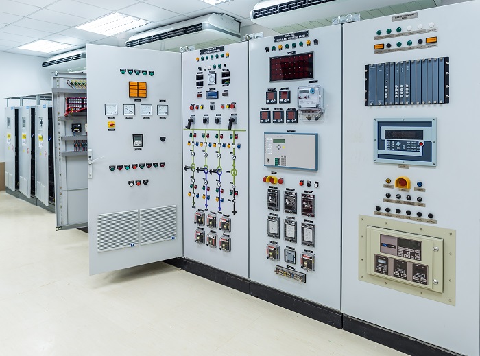
Fig. 1: Power substation electrical switchgear (Image: Shutterstock)
Megatrends in energy distribution automation
More and more energy operators are remotely managing energy distribution using the cloud. Their software platforms provide performance monitoring, data analytics, visualization, fault detection and diagnostics, and portfolio energy management. These automation systems can monitor several variables in real time and analyze historical data to adjust devices to provide energy management while complying with government regulations and tariff policies.
By networking equipment data to the cloud, analytics can be run in real time using advances in AI to determine action to be taken. Advanced distribution automation (ADA) extends intelligent control over electrical power grid functions at the distribution level and beyond. Electric utilities with supervisory control and data acquisition (SCADA) systems have extensive control over transmission-level equipment and have increasing control over distribution-level equipment via distribution automation. Energy distribution automation results in higher availability, serviceability, and predictive maintenance, as well as fault detection, isolation, and mitigation.
Energy automation system
Energy automation system architecture (Fig. 2 ) includes different layers for management, control, and the field. The management layer operates and controls the energy distribution from one central location, recording and optimizing data as necessary. Problems are spotted in real time so that action can be taken immediately. The control layer deals specifically with the equipment control at the hardware level. At the field layer, intelligent sensors and actuators collect data and perform tasks. Sensor and control systems embedded in the distribution system help signal the reduction or elimination of outage time, hot-running equipment, circuit-breaker trips, and flickering and blinking lights.

Fig. 2: Energy distribution automation system (Image: Maxim Integrated)
Technology enablers
Distribution automation (DA) systems use a variety of wired and wireless communication media, depending on the particular segment of the communication network. All this intelligence, networking, and control is enabled by phenomenal advances in hardware and software.
At the field level, it is manifested through controllers, sensors, I/Os, and actuators. A controller can include a programmable logic controller (PLC), motor/motion controller, or a distributed control system (DCS) using advanced processors and microcontrollers. Sensors can be either digital or analog and be used to measure temperature, humidity, vibrations, opens, and shorts. Actuators can control energy flow, temperature, humidity, and other parameters. Sensors and actuators communicate on wire or wireless gateways to the control center. They are powered by batteries or wired DC voltages, typically in the 5-V to 24-V+ range. Fig. 3 shows a transformer substation control panel with its switches, signaling lamps, sensors, and scales.
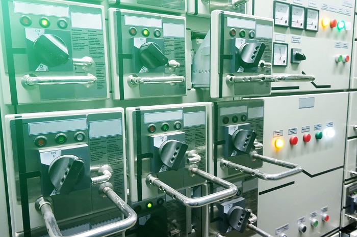
Fig. 3: Transformer substation with switches and sensors (Image: Shutterstock)
The controller receives inputs from sensors in the field, processes them, and drives the proper actuators. Today’s sensors and actuators are equipped with internal processors that make simple decisions locally without the need to escalate to the controller, thereby improving throughput and reaction time.
Challenges
The proliferation of intelligent, internet-connected equipment places new requirements on system hardware: reduced component size to fit additional electronics in the same chassis or even smaller chassis, improved energy efficiency to perform within the same or lower thermal budget, and increased electrical/mechanical safety and reliability to reduce downtime.
In summary, the challenges for the electronic components are:
- Higher energy efficiency
- Reduced solution size
- Increased safety and reliability
In the following sections, we will present a few examples of how power management electronics can come to the rescue in each case.
Solutions
High energy efficiency
The smaller PCB size that results from miniaturization presents a challenge for thermal dissipation. Thermal management options, such as heat sinks, are ruled out because board space is at a premium. Fans for forced airflow cannot be used due to sealed enclosures that prevent ingress of dust and pollutants. Therefore, it is crucial that the power-supply solution is extremely efficient while delivering higher power and occupying a smaller area than ever before.
Wired energy distribution field applications are characterized by a 24-V nominal DC voltage bus that has its history in old analog relays and remains the de facto industry standard. However, the maximum operating voltage for these applications is expected to be 36 V to 40 V for non-critical equipment, while critical equipment, such as controllers, actuators, and safety modules, must support 60 V (IEC 61131-2, 60664-1, and 61508 SIL standards).
Popular output voltages are 3.3 V and 5 V with currents that vary from 10 mA in small sensors to tens of amps in motion control, computer numerical control (CNC), and PLC applications. Thus, the obvious choice for control applications is a step-down (buck) voltage regulator (Fig. 4 ).
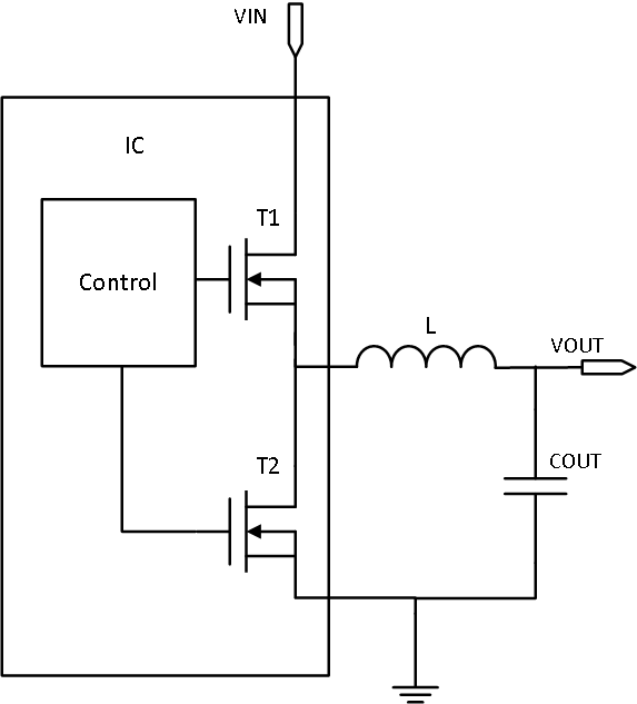
Fig. 4: Fully integrated synchronous buck converter (Image: Maxim Integrated)
Buck converters that achieve high efficiency for high-performance energy systems are shown under the energy efficiency category in Table 1 .
A word of caution on maximum input voltage
While 24 V is the nominal rail for many applications, for energy distribution, the operating voltage range must be carefully considered due to tolerances and abnormal transient voltages that cumulate to the maximum operating voltage. Available on the market today are 28-V, 36-V, 42-V, or 60-V input power management solutions. With a margin of only 4 V, 28 V is too close to 24 V to provide a reliable margin for most applications. Many standards require 60-V tolerance, removing the need to make a choice. It is tempting for many designers to choose a device with a 36-V maximum input. However, using a 36-V input is a high-risk approach for sensors and encoders working on a 24-V rail. Even if transient voltage suppressor (TVS) diodes are used for surge protection, they have a wide tolerance and could still expose equipment to excessive voltages.
Unless you know and have modeled every possible surge scenario resulting from long cables and PCB traces, use devices with a 42-V or 60-V maximum operating voltage even if the standard does not require it.
Reduced solution size
Sensors have become ubiquitous in the control environment. As they increase in sophistication and shrink in size, sensors are becoming more complex, requiring on-board voltage regulators to deliver power more efficiently with minimal heat generation.
How do you safely deliver low-voltage power to tiny sensors in high-voltage environments while minimizing solution size and maximizing efficiency? In this section, we will review a typical sensor architecture and provide a simple solution to this challenge.
Field sensor applications
Strategically placed throughout the distribution network, current, voltage, power, and temperature sensors provide multiple benefits, including identification of fault locations and causes to support quicker restoration efforts and proactive actions to avoid future unplanned outages. An intelligent sensor provides fault detection, captures key power quality data for day-to-day grid management, and supports renewable energy integration with the ability to detect and report on reverse power flows.
As an example, once a fault is detected, an actuator like the three-phase relay shown in Fig. 5 can automatically break the power line.
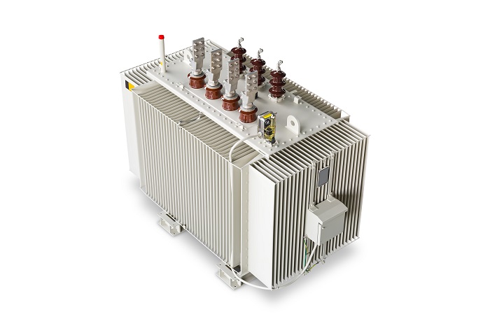
Fig. 5: 2.5-MW three-phase relay (Image: Shutterstock)
Sensor system
Sensors may be located anywhere on the field. The sensor “box” includes a front-end transceiver that handles data and routes power to a step-down voltage regulator. This delivers the appropriate voltage to the ASIC/microcontroller/FPGA, the sensing element, and communication device. A smart-grid sensor or overhead powerline sensor uses wireless or powerline communication. Fig. 6 shows an overhead sensor in a three-phase powerline.
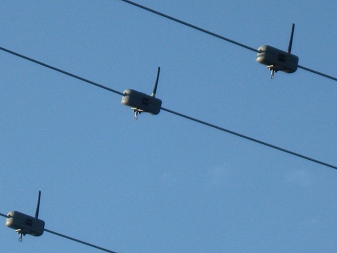
Fig. 6: Smart grid overhead line sensors ( Imagelicensed under CC BY-SA)
Safe low-voltage operation
Most sensors are powered by a 24-VDC power source. However, the field can be a very challenging environment, with long cables and strong electromagnetic interference that result in high-voltage transients. Accordingly, the step-down converter inside the sensor must withstand voltage transients of 42 V or 60 V, which are much higher than the sensor operating voltage.
As discussed before, for 24-V rails, it is best to rely on devices that have an operating maximum of 42 V. According to SELV/PELV/FELV (Safety/Protection/Functional Extra Low Voltage) regulations, an isolated device that handles up to 60 V is considered safe to touch. Protection above 60 V is provided with the addition of dedicated TVS devices.
Examples of power solutions that meet the requirements of building automation sensors are shown in Table 1 under the small size category.
Increased safety and reliability: matching a buck converter to a TVS
The power path of a typical sensor system is shown in Fig. 7 .
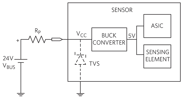 Fig. 7: Sensor power system (Image: Maxim Integrated)
If the 24-V bus is clean or has an electric noise level below the operating voltage of the front-end switching regulator, no protection is necessary (no TVS in Fig. 7 ) and a buck converter with a typical max input voltage of 36 V or 42 V is sufficient for this sensor design.
However, if strong electromagnetic interference is present, more severe measures are in order. A typical sensor power management solution utilizes TVS devices to limit the input voltage (VCC ) of the front-end buck converter. The associated input current peaks are reduced by the resistor RP , a parasitic or physical element in the electric path between the voltage transient’s source (VBUS ) and the sensor.
Let’s see how to select a TVS out of the LitteIfuse catalog as an example. The general characteristics of a TVS are shown in Fig. 8 .
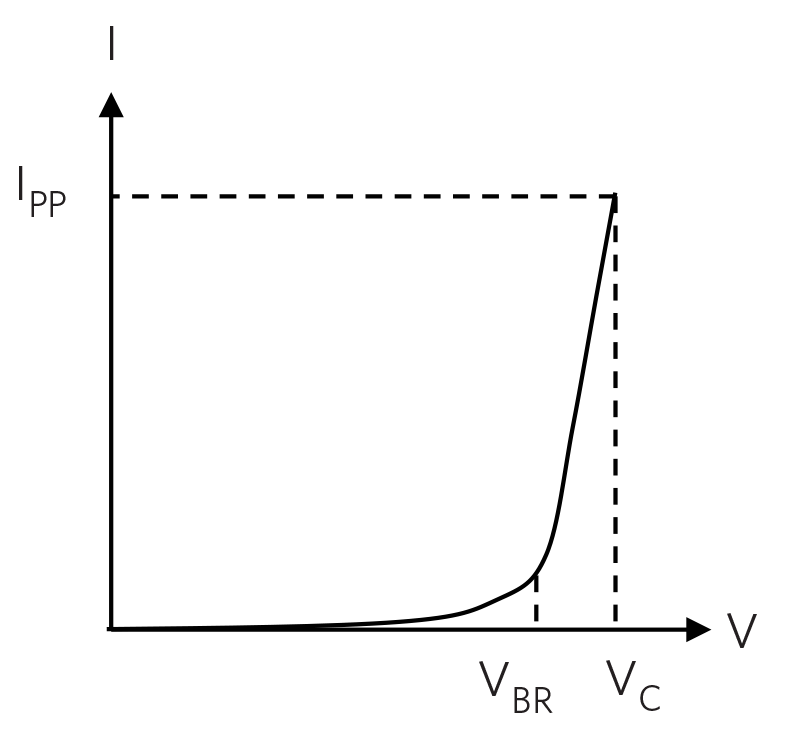
Fig. 8: TVS V-I characteristics (Image: Maxim Integrated)
The TVS device is an open circuit until the voltage across it reaches VBR. At this point, it starts to conduct current while its voltage rises slightly up to its maximum clamping voltage, VC , which corresponds to the maximum allowed peak pulse current, IPP . The product of VC × IPP is the maximum peak power that the TVS can handle (400 W for this TVS family). For effective protection, the TVS VBR must be above VCC(MAX) , while VC must be below the switching regulator input voltage breakdown.
Our VBUS supply is 24 V +25%, –20%, with 30 V maximum (VBUS(MAX) ). Ideally, with a 60-V-rated buck converter, a SMAJ33A with a minimum VBR of 33 V can be used (as well as a clamp voltage VC of 53.3 V, which is well below 60 V). This gives an operating margin of 3 V above VBUS(MAX) and 6.7 V below 60 V (Fig. 9 ).
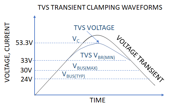
Fig. 9: Ideal TVS selection (Image: Maxim Integrated)
The fact that the buck converter must withstand 24 VDC and at least a 53.3-V transient removes a large group of buck converters from consideration. Examples of 60-V-rated buck converters are shown in Table 1 under safety and reliability.
Increased safety and reliability: isolation
Isolated DC/DC voltage regulators are found in the most diverse applications. Although an isolated solution is more complex than a non-isolated one, there is still an expectation for it to fit in a small space and be highly efficient. In this case study, we discuss the reasons for isolation in low-voltage power conversion systems.
According to SELV/FELV regulations, input voltages below 60 V are considered inherently safe to touch, but the need for isolation in this operating range is still pervasive for functional safety and reliability reasons. In this voltage range, the power supply electronic load, typically a very delicate and expensive microcontroller, needs protection. It could readily self-destruct if accidentally exposed to high voltage.
Isolation also prevents ground loops, which occur when two or more circuits share a common return path. Ground loops produce parasitic currents that can disrupt the output-voltage regulation as well as introduce galvanic corrosion of the conducting traces. This is a phenomenon that degrades equipment reliability.
As an example, a peak current-mode, fixed-frequency switching controller is shown in Fig. 10 . It is specifically designed for the isolated flyback topology operating in discontinuous conduction mode (DCM). The device’s advanced feature eliminates the need of an optocoupler for output voltage feedback and regulation. No-opto means less board space and high reliability because the inherently low mean time between failure (MTBF) optocoupler is out of the picture.
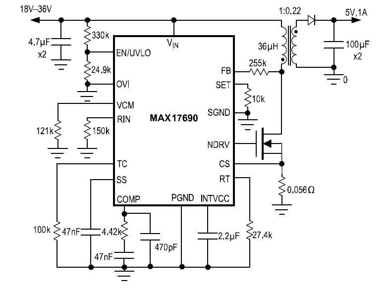
Fig. 10: No-opto flyback controller (Image: Maxim Integrated)
Increased safety and reliability: protection
Protection circuits are the unsung heroes of today’s electronics. The long electrical chain, from the AC line to the digital load, no matter the application, is interspersed with fuses and transient voltage suppressors of all sizes and shapes. While common issues like ESD protection and pin-to-pin short-circuits are handled within ICs, there are additional aspects to consider for safety and reliability.
Along the electrical path, electrical stressors such as inrush currents due to storage capacitors, reverse currents due to power outages, overvoltages, and undervoltages induced by inductive load switching or lightning, can damage precious electronic loads. This is true for microprocessors and memories, which are built with fragile sub-micron, low-voltage technologies. Layers of protection are necessary to handle these potentially catastrophic events (Fig. 11 ).
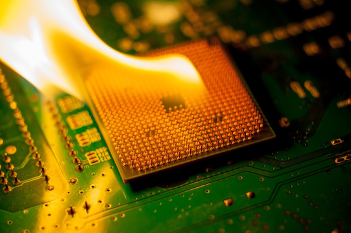
Fig. 11: Unprotected CPU on fire (Image: Shutterstock)
Protection electronics must handle fault conditions such as overvoltage/undervoltage, overcurrent, and reverse-current flow within the limits of its voltage and current rating. If the expected voltage surge exceeds the protection electronics ratings, additional layers of protection are added in the form of filters and TVS devices.
Integrated solution
Fig. 12 shows an integrated protection circuit that addresses overvoltage, undervoltage, reverse polarity, current limiting, reverse current, and short-circuit protection with all the benefits of an e-fuse and surge stopper. Designers can easily implement robust protection in their smart grid equipment and pass compliance with configurable pins to set features such as UVLO/OVLO, current limit, real-time voltage, current monitoring, current thermal foldback, and thermal shutdown.
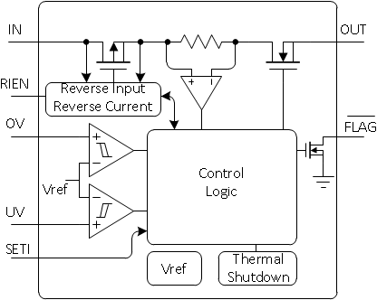
Fig. 12: Integrated protection in a single IC (Image: Maxim Integrated)
An example of a highly integrated protection IC is shown in Table 1 under the safety and reliability category. Table 1 is a summary of the power management approach for energy distribution automation.
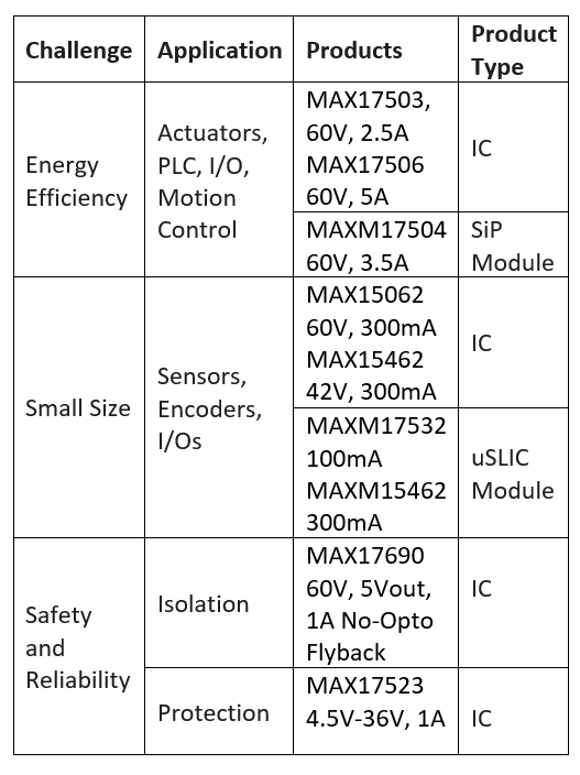
Table 1: Power management for energy distribution automation
Conclusion
As the current trend of automation and data exchange continues, it will rely on new technologies and approaches to achieve higher energy availability, serviceability, and predictive maintenance, as well as fault detection, isolation, and mitigation. The adoption of these technologies introduces challenges in terms of energy efficiency, miniaturization, and system reliability.
For each challenge presented, we showed how more efficient power management can improve the design of energy distribution automation systems. These power management solutions overcome the critical challenges faced by today’s energy distribution automation systems.
About the authors
Anthony T. Huynh (aka Thong Anthony Huynh) is a principal MTS of Applications Engineering at Maxim Integrated. He has 20+ years’ experience designing and defining isolated/non-isolated switching power supplies and power management products. At Maxim, he has defined 100+ power management products, including DC/DC converters, hot-swap controllers, power over Ethernet, and various system-protection ICs adopted by the world’s leading manufacturers. Anthony holds 7 U.S. patents in power electronics and has published numerous articles/application notes in this area. He has a B.S. degree in electrical engineering from Oregon State University and has completed all coursework for an M.S. degree in electrical engineering at Portland State University, where he also taught a power electronics class as an adjunct instructor. At Maxim, Anthony has authored and presented many customer and field training seminars in the power electronics area.
Nazzareno (Reno) Rossetti is an analog and power management expert at Maxim Integrated. He is a published author and holds several patents in this field. Reno holds a doctorate in electrical engineering from Politecnico di Torino, Italy.
Advertisement
Learn more about Electronic Products MagazineMaxim Integrated


