Choosing the right MELF can enable greater power handling in smaller spaces
BY JOACHIM VON DER OHE
Vishay BCcomponents Beyschlag GmbH
Heide, Germany
http://www.vishay.com/company/brands/bccomponents
Fixed linear resistors are commonly required in a diverse range of applications, from medical and aerospace electronics, to communications and automotive, to lighting and general industrial equipment. For both designers and specifiers of such components, the continuing progress of miniaturization has posed a challenge in terms of power consumption and system-level thermal management.

The ability of MELF resistors to handle pulse loads beyond 8,000 W is one reason for their popularity.
The challenge is to cram more power-handling capability into ever-smaller spaces, making the resistor’s power-handling ability a key datasheet quantity, not only in terms of dc and RMS dissipation, but also regarding a device’s ability to deal with single or repeated pulses of power. The ability to handle pulse loads beyond 8,000 W is one reason behind the continuing popularity of thin-film cylindrical metal electrode leadless face (MELF) resistors.
About the MELF
The nature of their construction means that such devices are fundamentally less likely to fail than their thick-film flat-chip counterparts. This is partly due to the nature of conduction in carbon or metal thin films, which are homogenous materials and therefore deliver much more uniform current distribution than thick-films based on a mix of different particles. But it is also assisted by the ability to implement a helical or meandered trimming strategy that ensures more uniform current within the film, and in particular eliminates hot spots caused at the conduction “pinch point” introduced by L-shaped trimming.
And finally, the resistive surface itself is about three times as large as that of a flat chip occupying the same board space. This popularity in a diverse range of applications has created a need for an equally diverse range of device families optimized for particular characteristics.
Carbon-film types provide pulse load capabilities of up to 10 kV; high-frequency metal-film versions can function at above 10 GHz; tolerances go down to ±0.02%; TCRs down to 5 ppm/K; and load life stabilities as low as 200 ppm are available. More recent developments combine high-frequency capability with high pulse-load handling, and, for military and aerospace requirements, established reliability grades are also available.
Choosing the right one
So, if pulse-handling capabilities are key, how is the designer to ensure the selection of the right device for the task, amongst this variety of performance indicators? The first fact to realize is that correct power-handling specification is not simply a question of avoiding catastrophic failures.
MELF components are often selected for applications in which a key factor is stability, an attribute that can be affected by the need to deal with pulsed loads. The most commonly quoted requirement in this regard (although some datasheets choose to ignore the attribute altogether) is the CECC/EN extended endurance test specification. This defines a permissible resistance change after 8,000 hours of operation with a film temperature of 125C, achieved by applying the resistor’s rated (P70) electrical load.

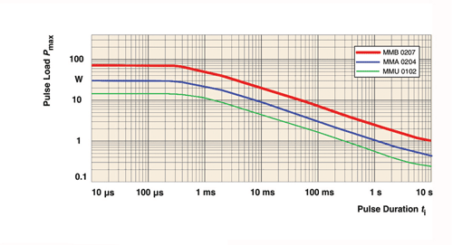
As duration increases, maximum peak power approaches rated power dissipation.
Whether considering limited, small resistance changes or potential catastrophic failure, there are three types of limits on the pulse loads which a resistor may be expected to withstand. First, pulses must be limited in peak power for any given duration; second, the average power of a repetitive pulse load may not exceed the rated power dissipation (often quoted as P70), including derating if required; finally, the maximum voltage amplitude of single and continuous pulses must be limited for high ohmic values.
Pulse-handling ability
A resistor’s ability to handle pulse loads is typically specified in terms of peak power for the pulse duration time of an equivalent rectangular pulse. The root of the process for the designer is therefore to calculate the energy of whatever single pulses are expected in the design, and then relate that to an equivalent rectangular pulse for comparison against the target specification of the device.
The equivalent rectangular pulse will have the same power amplitude as the expected real-world pulse; and its duration will be such that its total energy will be the same as that of the real-world counterpart. Two common scenarios for which the equivalent pulse must be calculated are a square pulse of some nature (this may be unipolar or bipolar, symmetric or asymmetric); and a decaying exponential waveform.
In the case of the square pulse, the energy is proportional to the peak power and pulse width of its parts. For the falling exponential case the equivalent time is simply half of its time constant. The power amplitude must be within the target device’s allowed specification for peak power for the calculated duration of the equivalent square pulse.
The behavior of the device at extremes of loading is highly dependent upon its materials and methods of construction. Typically, with very short pulse durations (around 200 to 300 µs), the maximum permitted peak pulse power reaches a constant value.
This is because the pulse is so short that there is no appreciable heat flow out of the resistive layer over the duration of that pulse. As duration increases, maximum peak power approaches the rated continuous power dissipation.
In the case of a repetitive pulse load, the value of the average power of the pulse train must be kept below the resistor’s rated power with appropriate derating. Using the established equivalent square pulse, the average power is proportional to its duration and inversely proportional to the period of the pulse train.
Resistor datasheets generally specify continuous pulse-load handling via pulse load diagrams. These typically show the maximum rated peak pulse load for a rectangular pulse shape with positive voltage amplitude: as with the case of single pulses, the designer must calculate the square pulse attributes which would be equivalent to the expected real-world pulse train, and read the appropriate values from the diagram.
By establishing the relationship between peak power dissipation and pulse width, pulse load diagrams allow the designer to check that the resistor they have in mind is suitable for operation at the pulse frequencies required by the application. This process can also be assisted by reference to a number of standard tests. As well as the CECC /EN specifications already referred to, the IEC standard lightning pulse can be useful in establishing a consistent measurement method for comparison.
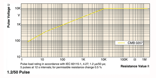
The standard, known as IEC 60 115-1, defines two different pulse shapes: known as 1.2/50 µs and 10/700 µs (as defined in clause 4.27). The first figures in these expressions (before the slash) provide a measure of pulse rise-time, while the second (after the slash) indicate the speed of decay (the waveforms themselves are relatively complex, so the figures are not exactly equal to the rise and fall times).

When specifying thin-film products, test results should be provided in graphical form as voltage limit curves. Devices must withstand five pulses of the first type with a period of 12 s, and 10 of the second pulses with a period of 1 min. For thin-film products the test results are shown in graphical form as a set of voltage limit curves. Some manufacturers provide curves only relating to failure to open circuit; others provide more useful data, with limits on changes in maximum resistance value, typically of 0.5%. ■
For more information on resistors, visit http://electronicproducts-com-develop.go-vip.net/passives.asp.
Advertisement
Learn more about Vishay Intertechnology


