MEMS microshutters for a new space telescope
’With measurement ambitions beyond that of its Hubble predecessor, JWST plans to see galaxies from the beginning of time
BY ERIC LYNESS
Mink Hollow Systems, Ashton, MD
http://www.minkhollowsystems.com
DAVID RAPCHUN
Global Science and Technology
Greenbelt, MD
KNUTE RAY
NASA Goddard Space Flight Center
Greenbelt, MD
http://www.nasa.gov/centers/goddard/home/index.html
The James Webb Space Telescope (JWST) is the next big telescope at NASA. More ambitious than the Hubble Space Telescope, its predecessor, the JWST will be placed by NASA at a stable Lagrange point approximately one million miles from the earth.
This telescope is the next stepping stone toward understanding the universe and studying the Big Bang theory at NASA. The next major project milestone is the overall Critical Design Review, which is currently scheduled for March 2010; if all goes well, JWST should launch in the next decade.
The primary instrument on the telescope is the near infrared spectrometer (NIRSpec), developed by the European Space Agency (ESA) with major contributions from NASA. The spectrometer observes thousands of distant galaxies to probe the epoch of initial galaxy formations in the universe. To measure numerous faint objects, the instrument must simultaneously observe a large number of objects in previously unknown positions.
To observe objects at these positions, NASA developed the microshutter array, a 171-x-365 matrix of 100 x 200-µm shutters that can open under random access control. Four of these microshutter arrays in a 2 by 2 matrix create a programmable transmission mask of about 250,000 shutters, which allows NIRSpec to simultaneously target more than 100 faint objects, proportionally improving the efficiency of this major scientific facility.
Designing microshutters
A microshutter is a µm-scale rectangular door that opens to let light pass through and closes to block it. The shutters, which pivot on a silicon-nitride flexure, are actuated magnetically with the help of magnetic coating and latch electrostatically through electrical connections.
When the engineers began working on this project, manufacturing shutter arrays was a new and complex process that was still under development. NASA manufactures the shutters in arrays with 365 columns and 171 rows, for a total of more than 62,000 shutters per array. We mounted the shutters on a substrate and wired the array in a grid so that we can assert its rows and columns to address each shutter.
To open a shutter, we passed a magnet across the front of the array while applying high voltage to the row and column of each shutter. The magnetic field opened the shutter, and the static charge at the intersection of the row and column held it open.
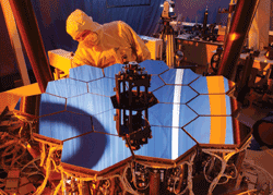
We fabricated each shutter array to test some aspect of the overall design (Fig. 1 ). Tests in this facility inform the further definition of the fabrication process. We developed the software that controls the vacuum chamber, shutter control instrumentation, cameras, and other apparatuses to evaluate array performance.

Fig. 1. For testing the microshutter design, NASA used a fully functional, 1/6th scale model of the JWST mirror in an optics test bed.
Testing with this system revealed that uncontrolled shutter release limits shutter performance. In this uncontrolled approach, one closed a shutter by turning off the power to the row and column of the shutter. With each approach, the shutter impacts its light baffle in a way that significantly limits its lifetime.
The development team decided that we should release the shutters in synchronization with a passing magnet so that the magnetic field cushions the impact as the shutter closes. A test chamber completed in 2005 includes this new synchronized latching-and-release capability.
Microshutter control system
The microshutters must function reliably for up to 100,000 cycles on different shutter designs. Instead of testing for years, the new test chamber must cycle the shutters rapidly. The motor rotates at up to 240 rpm; thus, the sled, connected to the motor with off-center cables, crosses back and forth in front of the shutter array four times per second. The control system needs to latch or release each of the 365 columns of the shutter array exactly as the magnet passes. To get an idea of the precision and speed required, imagine that each column of the shutter array is a slat 1 in. wide in a picket fence that is 30 ft long. The magnet would be like a jet plane moving past it at more than 700 mph and only 3 ft away.
To control the shutters, we have to communicate with the control electronics and custom high-voltage shift registers. The new system also needs to rapidly communicate and provide utilities to test and verify many operations of the 584 chips. The system must meet all of these control requirements and be fail-safe. The tests run for days at a time, opening and closing all 62,000 shutters 240 times per minute. If the system loses synchronization, the loss can damage the shutters in just a few minutes.

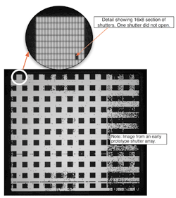
Fig. 2. An early prototype turns up a shutter failure that changed the way in which the system would operate.
So the challenge was to synchronize the motion of a magnet moving more than 1 m/s with the opening and closing of tens of thousands of hair-sized microelectromechanical system (MEMS) microshutters.
One approach to meet these requirements, would have been to design and manufacture a custom chip, which would have entailed significant design resources and risk.
Instead, the approach the team adopted was to use the LabVIEW FPGA Module. We selected a PXI chassis and controller containing a PXI-7813R reconfigurable I/O module and used the LabVIEW FPGA Module to perform shutter control. Using the NI FPGA Module and the reconfigurable I/O module allowed us to precisely and deterministically pinpoint the position of the magnet and the proper outputs to control the MEMS microshutters in perfect synchronization.
The control design
The entire system contains a host computer that controls the test chamber, a field-programmable gate array (FPGA) host program that runs on the PXI controller, and FPGA software that runs on the reconfigurable I/O module. With the FPGA host interface, engineers can calibrate the system and perform manual control functions, create and download bitmaps to write to the arrays, and run self-test diagnostics on the other functions of the 584 chips.
The FPGA software reads the position of the magnet from a quadrature encoder or an absolute encoder. We placed the encoder-decoding algorithm in a single-cycle loop running at 40 MHz to ensure it does not miss any steps. After some filtering to remove jitter, we placed the position value in a first-in-first-out memory buffer (FIFO). Another loop on the FPGA reads the FIFO and determines what to do with the shutters based on the current location of the magnet. This state machine communicates with the 584 chips using the protocol to turn the appropriate rows and columns on or off.
If the FIFO overflows, the state machine controlling the shutters is not going fast enough. The software indicates a synchronization error to the host computer so the system can shut down.
This algorithm works very well and has become the foundation for control experimentation on the shutter arrays. As engineers develop new ideas to improve shutter operation, we can easily add or change algorithms in the state machine block.
The LabVIEW FPGA Module and PXI-7813R saved us hundreds of man-hours and thousands of dollars over developing a custom chip. In addition to saving costs, the control algorithm is also inexpensively modified to improve testing, explore shutter issues, and further the development of the NASA microshutter arrays. ■
Advertisement
Learn more about National Instruments


