Microconverter in solar photovoltaic systems for residential applications: a cost-to-benefit comparison
Find out what the benefits and challenges of adding a micro-converter in a residential PV system
BY DAVE FREEMAN and NAGARAJAN SRIDHAR
Texas Instruments, Dallas, TX
www.ti.com
Even during tough economic times solar installations continue to accelerate. In a recent iSuppli report (http://tiny.cc/qg0q9) Germany is expected to set a new installation record of 6.6 GW. Another record of 9.5 GW for 2011 is predicted, even in the face of reducing the feed-in tariff (FIT) later this year. iSuppli predicts that worldwide solar growth will be more than 93%. Much of this growth is stimulated from rebates, FIT programs, and tax incentives. Nonetheless, solar continues to grow.
As part of this growth, especially in urban areas, optimal south-facing roofs will become harder to find. In many cases for existing residential houses, the roof line was chosen more for aesthetics, and not much thought was given to installing photovoltaic (PV) modules. However, homeowners now may be attracted by the rebates and other incentives to place solar panels on their roofs. In many cases the rebates are based on 1,000 W/m2 power output, and not most likely what will be delivered for a particular installation.
Still, the homeowner will want to maximize the total energy from their installation, especially if there is a FIT in play. One method to achieve this is to install module electronics that track the maximum power point for each module under the prevailing conditions.
This article quantitatively evaluates the improvements of adding a microconverter in a residential PV system that deals with the challenges of nonoptimal conditions, and to evaluate the real-world benefit over the cost incurred by the system owner. It focuses on residential and urban applications.
PV module behavior
Solar cells, when connected together in series or parallel, comprise to form a PV module. In a typical residential or grid-tied application, one common way to build the PV system is by connecting modules in series to form a string, called a PV array, in order to deliver maximum power occurring at the maximum power point (MPP) of the I-V/PV curve. The ability to extract power is reduced under nonoptimal conditions such as shading. One school of thought is to completely eliminate the nonoptimal conditions through proper installation. This is true for grid applications such as a utility farm, generally located in an open and clean environment that is not exposed to such unpredictable and various field conditions. However, as the price of solar modules decrease, the number of residential and urban installations is increasing.
Examples of residential installations include rooftops and in windows, and urban installations include public transportation locations. Compromises can be expected due to occasional in increases the cost of ownership, namely the cost/W, a key measure in this highly competitive energy market. Module electronics is a way to mitigate this problem. Thus far, module installations in residential applications have been based primarily on a centralized or string inverter concept. However, if some portion of one or more array modules is nonoptimally irradiated due to shading, module angle or dirt from the road, system optimization can be compromised. Here is why:
Consider a simple residential system where all modules are connected in series. If one module is partially shaded, its maximum power current drops. However, it also reduces the current over the entire string, resulting in an efficiency drop for the system. A recent trend to minimize this problem is to move towards a microconverter or a microinverter based topology. Both topologies are usually employed at a module level. The advantage of this topology is twofold: (1) it isolates any nonoptimal condition to that module alone; and (2) it improves system power output under nonoptimal conditions.
Key challenges to make this topology successful are to ensure the highest efficiency of these systems, and to have a low cost-to-benefit ratio. Several articles have been published that discuss the value of such a topology. It turns out that there is a trade-off between cost and benefit. There have been several claims of improvements as high as 25%. Therefore, it is important to quantify this improvement under the real-world conditions described earlier. The incremental power improvement under nonoptimal conditions will help determine the true benefit over the cost incurred by the system owner.
PV array configuration and characterization setup
Figure 1 shows the PV module configured in our facility.
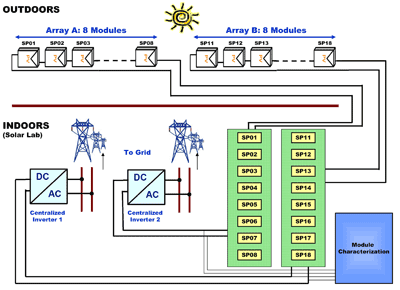
Fig. 1. PV array block diagram.
The work is setup in an urban environment where conditions are not always optimal, as our array is located in the middle of commercial buildings and next to an elevated high-density traffic network. Light intensity is measured using a cosine corrected pyranometer. The ambient temperature for each module is measured using a thermister.
Microconverter study
For the microconverter study, we used a buck topology.
Microconverter efficiency
The efficiency test is to use one module and measure the maximum current, voltage, and power with and without the microconverter under same irradiance conditions with no shading.
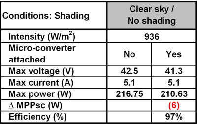
Table 1. Microconverter efficiency.
A 3% loss is seen (Table 1 ) indicating that for residential and urban applications, the owner may not want to install a microconverter on modules that are expected to be exposed only to optimal irradiance conditions. Doing so will impact the overall installation cost.
A similar trend is seen at a system level, which has two modules connected to a microconverter (Table 2 ).
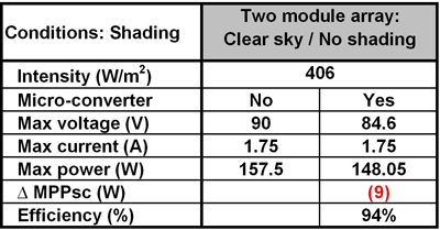
Table 2. Array efficiency with microconverter.
Sequence of testing under various scenarios
The method of testing various scenarios is done using the sequence shown in Fig. 2 .
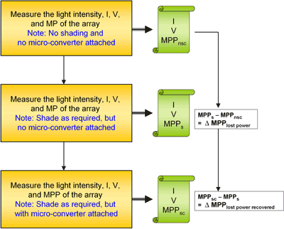
Fig. 2. Testing method.
The key metric to focus on is the percentage of lost power recovered obtained from the ∆ MPPlost power recovered , defined as the lost system power gained with a microconverter in a module under nonoptimized conditions, divided by the power lost by the PV system without the microconverter. Scenario 1 : Single-module shading (traffic light/street light application)
Microconverters are seldom used for traffic and street light applications (primarily with the advent of LEDs) that are widely being deployed across the globe using a single solar module as the energy source with battery as the storage element under a normal clear sky condition (efficiency loss). The same is true under a shaded condition, since the total energy from the module can never exceed the collection efficiency of the module (Table 3 ).
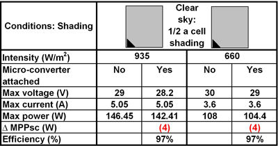
Table 3. Single-module under nonoptimized conditions.
Array scenarios : Shading for a three-module array
Here, shading is done on Module 1 connected in series with two other modules (Modules 2 and 3) that have no shading, and no microconverter attached. Each module is made of three substrings (24 cells in series within a substring) connected in series. When a module is not connected to a microconverter, the current goes through a bypass diode connected in parallel that turns on when conduction is blocked through the solar cells in that substring. Therefore, the I-V curve of an un-shaded module is simply the sum of the open circuit voltages of the individual I-V curve of three substrings (or bypass diodes) current staying constant.
Scenario 2 : Single substring shading
I-V and PV plots of different cases of substring shading on Module 1 without the microconverter in the three module array are shown in Fig. 3 . There are two power peaks competing for global MPP, one close to 3Voc,module and the other close to 2.66Voc,module . The 2.66Voc,module peak is due to the voltage drop across the bypass diode as opposed to the drop across the shaded substring. The height of the peak close to the 2.66Voc,module location increases with the increasing percentage of cell-shaded (see Table 4 ). However, the peak locations remain the same. Table 4 also shows the percentage of lost power recovered for the array when Module 1 is connected to the microconverter. From our study, data indicates that the percentage of lost power recovered is the highest for the 18% shaded range. This is due to the height of the two peaks getting closer to each other.
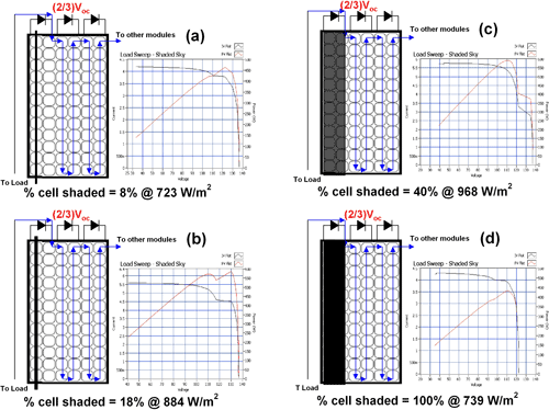
Fig. 3. Single substring module shading.
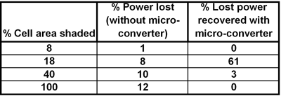
Table 4. Substring module shading.
Scenario 3 : Module shading
Figure 4 shows I-V and PV plots for a variety of user cases for the module shading scenario on Module 1 without the microconverter in the three-module array.
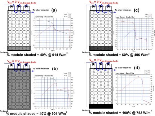
Fig. 4. Module shading.
Two power peaks are competing for global MPP, one close to 3Voc,module and the second close to (3Voc,module – nVoc,substring ), where n is the number of substrings shaded. Here, n = 3 for module shading. This positions the second peak close to 2Voc,module which is the dominant peak. The percentage of power loss for the cases in this category are significantly higher (Table 5 ) when compared to cases in the substring category.

Table 5. Module shading (n = 3).
Moreover, the percentage of power loss does not change with the percentage of the module shaded. The reason is that the percentage of module shading only modulates the height of the peak close to 3Voc,module , which in this category is the less dominant peak. Table 5 shows the percentage of lost power recovered for the array when Module 1 is connected to the microconverter. This indicates that it is higher for the 40% shaded range and decreases with increased cell shading per substring. Note that the height of the local maxima are getting close to each other at the 40% cell area shaded regime.
Discussion
From the above scenarios, you can see that:
• There is an incremental increase in the overall system (array in our case) power (∆ MPP lost power recovered) with the microconverter connected to the module affected with the nonoptimal condition. This is true for all shading conditions evaluated in this paper except for 100% shading, or for very little shading (8% or below). This is due to boosting the current for the shaded module, which in turn increases overall system current.• The module shading scenario appears to be the most beneficial in terms of lost power recuperated. The rationale is that the microconverter is connected across the module, that is, across all the three substrings. Hence, the current path and the voltage regulation takes place using the converter (buck in our case). Alternatively, if the microconverter was connected across each substring, all scenarios benefit from the presence of a microconverter.
Furthermore, in terms of scenarios, many cases are possible such as uniform and nonuniform, fully and partially shaded conditions, as well as nonshaded conditions with microconverter attached. However, the question of each occurring at equal and/or high probability is always arguable.
Benefit-to-cost analysis
Current cost of a module is around $4/W. This is an important number for payback analysis, which is essential for any PV system owner. With the cost of this module fixed, the next PV system bill of materials investment is panel electronics. If an owner is interested in installing a microconverter, a key decision is to understand the number of microconverters needed for the system. This is based on the number of modules likely to be shaded – which needs to be tied to the price of the microconverter. Based on the above results, and using the current cost of $4 per Watt, the price can be estimated.
For every Watt requirement, the PV system owner pays $4. Therefore, averaging the power gain from the different scenarios (including single and array, with and without shading), the boost in power is around 9 W. This means that the price is estimated by $4 x 9 W = $36 for a microconverter with an efficiency of around 95.5%. However, with a higher efficiency microconverter of about 99%, or an improvement of 3.5%, the power extracted could go up to 3.5 X 2 W = 7 W (from Tables 1 and 2, 1% loss is equivalent to a loss of 2 W). The resulting price goes up to $4 x (9 + 7) = $64 per microconverter.
If a similar calculation is done for the module shading scenario alone, the price climbs up to $184 (based on an average of 46-W improvement for a 95.5% efficient microconverter). However, to simply expect module shading to be the only likely scenario or one with a higher probability to occur is questionable. Hence, it is important to take into account the average of all scenarios, if not the worst case, assuming equal likelihoods of occurrences.
This estimate, even though it might appear to be pessimistic or on the lower side, gives a perspective of the current microconverter performance on a PV system using a realistic scenario for residential and urban situations where panels can be subjected to a variety of shading, and dirt.
Future trend
With module prices expected to go down to $2.5/W in the next two to five years, the microconverter needs to follow one of two strategies: (1) the microconverter price will follow the same trend as the module price; or (2) which is more likely, is that microconverter technology will improve through the use of GaN FETs to eliminate some of the losses. This could boost efficiency to as high as 99%. With the right technology as the driving force, microconverters could establish itself as a vital player in the PV energy chain. This in turn would alleviate some of the price pressures currently determined by the module prices.
Future opportunities on nonoptimal conditions will need further exploration using microconverters such as tilt angles and building for integrated photovoltaics applications. ■
Advertisement
Learn more about Texas Instruments


