MIPI display standards for mobile Internet devices
The latest display interface aids handheld designs
BY ALLEN TUNG
California Micro Devices
Milpitas, CA
http://www.cmd.com
As mobile Internet devices gain in popularity, more and more manufacturers are competing to design the latest and greatest products. Low power has always been the main concern for handheld devices, and this includes their display electronics. Intel is supplying a majority of processors for these devices, according to market research firm iSuppli. To replace the traditional, cumbersome RGB parallel bus, Intel makes both LVDS and MIPI DSI interfaces available in the latest release of the Moorestown processor.
MIPI DSI (Mobile Industry Processor Interface, Display Serial Interface) is the latest display standard for portable handheld devices. With a scalable data-lanes configuration, the interface is able to transfer data at 3 Gbits/s and, with low differential swing voltage, the interface has very low emission levels. ECC and CRC checksum embedded in the packets allow the receiving client to perform error correction and recovery.
Implementation underway
Display manufacturers started device implementation when MIPI DSI and DCS (Display Command Set) standards were becoming more mature in the past year. Due to the complexity of mixed-signal design, plus the uncertainty of the volume demand ramp-up time, only a few MIPI-integrated displays are available to manufacturers of mobile Internet devices. Initially, most display manufacturers preferred to use a display bridge solution, which converts a high-speed serial interface to a conventional parallel RGB interface, to test the market reaction of the product before committing to integrate both the MIPI client and the display in one unit.
MIPI supports two display standards:
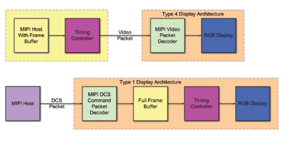
* DSI video mode (see Fig. 1a ). This operating mode is similar to a traditional RGB interface; the host is required to constantly refresh the display client. Instead of using dedicated digital signals to signify synchronization information, these signals and RGB data are represented in packet formats and transmitted over the MIPI bus. Because the host is required to refresh the display periodically, the display does not need a frame buffer.
* DCS command mode (see Fig. 1b ). The MIPI host sends pixel data stream to the display using the display command set packets. The display should have a full frame buffer to store all pixel data. Once the data is in the display’s frame buffer, the timing controller fetches data from the frame buffer and puts on the display autonomously. The MIPI host is not required to refresh the display constantly.

(a) MIPI video-mode operation block diagram. (b) MIPI DCS command-mode block diagram.
Pros and cons of the modes
Each operating mode has its pros and cons, based on cost and power consumption. Video-mode display architecture cuts the cost of the frame buffer. However, the host constantly sends DSI video packets in high-speed mode, consuming a significant amount of average power.
Ideally, when display content does not change (or does not change frequently), the system’s central processor should switch to low-power mode, and the link between the processor and the display should be activated as needed. Because of this host-refresh requirement, part of the central processor and memory interface needs to remain active, and this could cause the system not to reach its best power budget.
On the other hand, the command-mode display architecture allows the display to refresh itself directly from the full frame buffer. However, integrating a full frame buffer on a display system is always costly, especially for a high-resolution display that is demanded by most consumers today. This results in a large interface chip die size. Display manufacturers might also need to have the display controller implemented with a specific amount of frame buffer for each display resolution.
For both video-mode and command-mode display architectures, it is usually necessary to program the display controller register settings to accommodate different display resolutions, aspect ratios, and operating modes. MIPI does not define any standard protocol to access these internal registers, so different display manufacturers have come out with their own manufacturer-specific commands.
To eliminate the hassle of developing various vendor-specific codes, certain vendors prefer the display to be able to self-initialize to a working state such that the MIPI host does not need to configure the display. In this case, the display usually has a PROM with the parameters. This is a convenient feature, and the PROM also occupies a significant amount of space on the silicon.
Main considerations
For best overall system area utilization, device manufacturers also need to consider the following:
* They should integrate high-efficiency LDO power supplies internally. Only one commonly available external voltage input should be connected to the display system.
* For a device generating clock frequencies based on an internal PLL, an external reference clock input is often required. This reference clock input can range from 32 kHz to several megahertz. D-PHY is a scalable, low-power, high-speed physical layer on which several MIPI interface standards will be based. Some D-PHY timing parameters also require a reference clock as a measurement unit. Combining the reference clock usage, a clock in the tens-of-megahertz range is a more practical frequency. Usually an internal oscillator generates a very-low-frequency clock as the reference clock feeding to the PLL, which will multiply this to the target frequency for the display controller’s D-PHY logic. ■
For more on display intefacing, visit http://www2.electronicproducts.com/DigitalICs.aspx.
Advertisement
Learn more about California Micro Devices


