By KEVIN PARMENTER,
VP Applications Engineering,
Excelsys Technologies, North America,
www.excelsys.com
Complex electronic systems in industrial and medical applications require the use of many dc-voltages to power a host of subsystems, including computing devices, memory, display, electromechanical actuators, sensors and many others. Depending on the application, the power supply will require compliance with stringent standards and a number of international regulations.
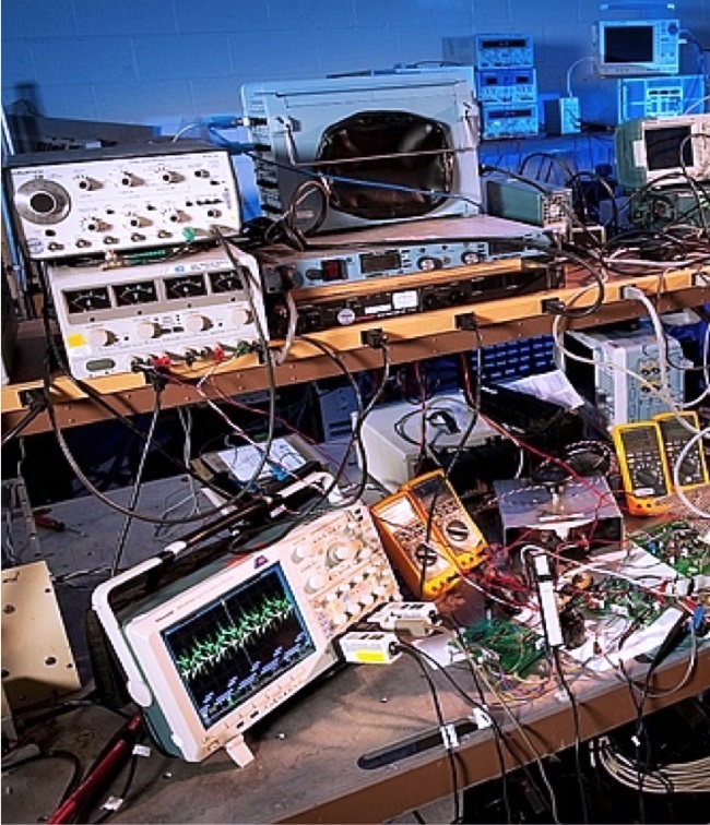
The traditional development process, utilizing an array of bench power supplies (Fig. 1 ), provides a degree of flexibility as the design progresses and requirements change. But the bench supplies do not accurately reflect the real-world conditions that the final system will experience. Consequently, there is an added element in the design cycle required to integrate power supplies into the system design that enables them to meet both the operational needs as well as compliance with the appropriate standards.
System engineers must focus on the core technologies of their design, which often results in the leaving the integration of the power supply into the system to the end of the design phase. As the design moves toward conclusion, the engineers are confronted with finding a way to “fit” the power supplies into the system.

Fig. 1: Example of system design project using bench power supplies, each powered separately.
Incorporating the power supply into the final system configuration begins with dealing with issues of space, weight and thermal considerations. In addition to these basic requirements, bench supply development doesn’t address a whole range of other considerations, including:
Global standards on energy efficiency are increasing at a staggering rate. There are 21 energy-efficiency regulatory agencies and standards in North America alone. The regulations cover both operating efficiency and standby power consumption. Some standards are mandatory; others are guidelines.
The PSMA (Power Sources Manufacturers Association) has published and maintains a comprehensive database of global energy-efficiency standards. They can be viewed at www.psma.com
Safety approvals
Power supplies fall under the IEC60950 (ITE) and IEC60601 (medical) standards for safety. The standards cover leakage current, circuit board creepage and clearance for starters and a plethora of other considerations. For medical applications, strict patient safety standards also apply.
EMI/RFI emissions
Standards for both conducted and radiated emissions are becoming stricter, due to an ever-increasing number of wireless devices and systems in both industrial and medical applications. Radiated emissions from power supplies must be limited to reduce potential interference to other proximate devices, to reduce interference to the device from other sources, and to reduce self-jamming of the product by its own emissions. The addition of industry-specific filters in the system is often a good idea at the system level. Even if the power supply does not need it to comply with some standards, systems may need them in certain end applications such as MIL STD 461F. There are many specific filters targeted for medical (low leakage), industrial and Hi-Rel/defense/aerospace (MIL STD 461F, typically) compliance. In these cases, it’s best to work with the power supply applications team collaborating with a well-known filter supplier in order to achieve first-pass success in the EMI compliance certification lab.
Power line variations
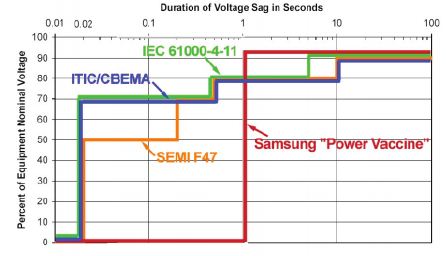
Continuous operation under varying line-voltage conditions, such as holdup time during short-term voltage sags and longer-term brownout conditions, are mandated by industry standards. The most common standard is IEC 61000-4-11. (See Fig. 2 )

Fig. 2: Sag immunity requirements for common power supply standards.
In some applications, even more stringent requirements are prescribed. For example, in semiconductor processing applications, the SEMI F47 standard for the semiconductor equipment industry requires operation (sag immunity) for even lower input voltages. And one of the most stringent standards, the “Power Vaccine,” requires ride-through for short-term voltage interruption.
Reliability
Always a principal expectation in Hi-Rel applications, uptime demands for electronic systems is becoming increasingly important in consumer, industrial and medical applications, as well. System downtime can be costly, so power supplies must have proven reliability. The required mean time between failure (MTBF) and mean time to failure (MTTF) are calculations that can only be provided as the result of actual test results. Simulations are worthwhile, but demonstrated data and information from field returns over time, as well as highly-accelerated life test (HALT) and highly-accelerated stress screening (HASS) testing on the product, is even better. The MTBF calculations based on Telecordia SR332 – MIL STD 217 is the usual and customary standard in this case.
Isolation
To assure compliance with leakage requirements in magnetics, as well as creepage and clearance requirements in optical and other isolation schemes, requires hi-pot (dielectric) testing of the power supply. For medical applications this is often 4-kVac with margin, which means that testing is often done at over 6 kV to ensure margin. Additionally, 2x MOPP (means of patient protection) is becoming commonplace in the industry.
Input surge testing
There are many input transient surge tests, depending on what is necessary to achieve compliance. Transients and surges can prove to be huge problems since a proximity lighting strike or an emergency generator in a hospital with centrifugal contactors can unleash havoc in systems. Although commercial power supplies have protection installed in them, some systems need additional protection to survive these events. There are numerous standards and specifications; but, again, it is best to work with a power supply manufacturer’s applications team to ensure meeting the requirements of a specific industry or application. As medical electronics systems are deployed into emerging economies where utility power is noisy and unpredictable, it is best to pay close attention to these considerations at the systems level.
Warranty
Ultimately, the power supplies that will be built into the final system should be designed to operate for the life of the system. Commercial power supplies typically have warranties that essentially speak to the manufacturer’s willingness/ability to guarantee the quality and performance of its supplies. The longer the warranty, the better chance the unit will meet this objective. Although we have touched on just a few of the concerns that can affect the system, there are even more environmental issues that are often covered by a good warranty, with five-year warranties becoming a benchmark.
Designing with modular, configurable power supplies
Modular, configurable power supplies are designed with a base unit that is designed to meet the operational standards required of the specific application. This type of power supply has the capacity to accommodate multiple output modules with expected power outputs and voltages needed; input/output isolation requirements; operational features; and advanced functions, such as sequencing. The compelling benefit of this approach is simply this: Upon completion of the bench design, the power supply requirements are fully incorporated and transferable to the system production without further design requirements
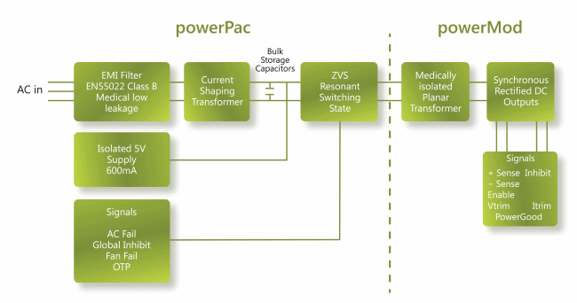
Figure 3 provides a functional description for a modular, configurable power supply comprising a base unit and a selection of DC output modules that provides a completely modular and configurable system power solution.

Fig. 3: Operation block diagram of modular, configurable power supply
The base unit consists of a semi-enclosed chassis containing circuitry for an off-line single-phase AC front end, EMI filter, cooling fan, customer interface and associated housekeeping circuits.
Input ac-voltage (L1/N, L2 and GND) is applied to an IEC320 type input connector and then through an EMI filter designed to meet EN 55022 Level B. For medical applications, the EMI filter also ensures the power supply meets the low earth leakage current requirements of EN60601-1 (3rd Edition). An active soft-start circuit limits inrush current. This stage is then followed by a high-frequency switching input current that shapes the boost converter feeding the ZVS (zero voltage switching) resonant switching stage.
The ZVS stage supplies power to the selected dc-output modules that provide the desired low-voltage, regulated outputs. This results in reduced size for magnetics and capacitors, excellent line and load regulation, wide adjustment range for output and low EMI/RFI emission.
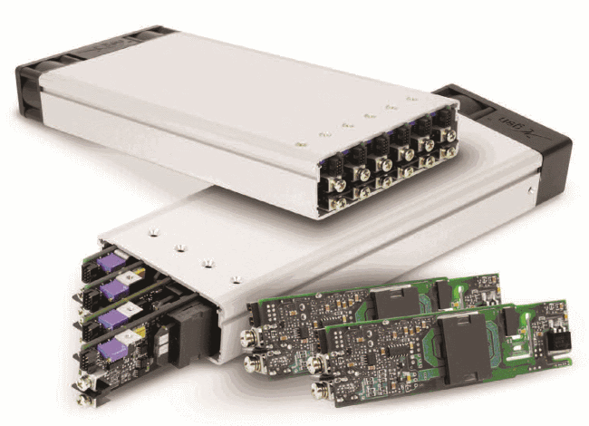
The UltiMod series (Fig. 4) from Excelsys Technologies is an example of a modular, configurable power supply design offering system developers a comprehensive power supply solution that can be applied from the earliest stage of product development and then ported seamlessly into the final system configuration.

Fig. 4: 1U-packaged UltiMod series power supplies are offered in 6- and 4-output versions.
The UltiMod Series is designed for highest efficiencies (up to 91%) and consists of two input ac front ends (powerPacs) and a wide range of dc-output modules (powerMods) in a compact 1U form factor package. All come with a five-year warranty.
There are many issues involved in integrating power supplies into system design. Three typical approaches: custom, in-house and standard off-the-shelf designs are often implemented at the end of the system design – and they have the serious drawback of causing major disruptions in the process if the power supply requirements change, which they often do. An alternative is to use a modular, configurable power supply from the very outset of the project. This approach often results in lower development costs and a dramatic reduction in time to market.
Selecting an experienced supplier that understands the myriad safety and environmental requirements is vital. Backed by a five-year warranty, the UltiMod Series offers a truly cost-effective example of this type of solution. For more information, please visit www.excelsys.com.
Advertisement
Learn more about Excelsys


