Monitoring and protecting smart meter circuitry and communications
It is important for design engineers to consider reliable circuit protection early in the design cycle
BY MIKE SMITH
Staff Field Applications Engineer
Bourns
www.bourns.com
The smart grid is the next generation of the utility framework that converges utility providers, telecommunications infrastructure and information technology. Striving to take the utility delivery systems into the 21st century, the smart grid utilizes computer-based remote control and automation. Seamless communication between utility companies and their end users for a true “end-to-end” smart grid is the ultimate objective. Support for the smart grid became federal policy with the passage of the Energy Independence and Security Act of 2007 (EISA). EISA provided the legislative support for the Department of Energy’s smart grid activities and reinforced its role in leading and coordinating national grid modernization efforts. Smart grids received further support with the passage of the American Recovery and Reinvestment Act of 2009 which set aside $11 billion for the creation of a smart grid.
Located at the end-user’s location, a smart meter is one of the key application elements of the smart grid. Smart meters are designed to allow two-way, real-time communication between the utility substation or headquarters and the end user. Smart meters are hybrid, telemetering devices combining measurement, processing, and recording with communication functions. Available with numerous communication protocols, smart meters essentially transmit resource consumption information via a network back to the local utility for monitoring and billing purposes.
Replacing traditional meters with smart meters poses several challenges including the management of numerous communication protocols, deploying systems that must meet varying global standards, and protecting the communication and smart meter circuitry. As the smart meter market gains momentum, how can designers ensure that reliable circuit protection is in place to safely monitor and protect smart meter circuitry? What are the various important circuit protection standards requirements needed throughout the meter system? This article will present an example of a combination solution that integrates shunt resistors for current measurement, and transient voltage suppression (TVS) diodes, gas discharge tubes (GDTs), fuses, and positive polymer temperature coefficient (PPTC) devices that satisfy the need for protection of internal signals and communications interfaces.
The basics of smart meter design
Smart meters provide metrology by measuring quantities of voltage, current, pressure, velocity, temperature, or flow rate, and communicate this information to the utility. Compared to traditional meters, smart meters record consumption in intervals of an hour or less. The advanced metering infrastructure (AMI) of smart meters provides two-way communication between the utility and the user, and AMI supports remote reporting. There are three primary elements to smart meter installations: energy awareness (providing cost signals to the end user device), energy response (allowing the end user device to respond to the price signals) and energy emergency (ability to provide immediate response to power shortages).
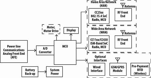
A power system, microcontroller, and communications interface are the three main internal areas of a smart meter design. The power system has a switched mode power supply and battery back-up to ensure the metering electronics remain powered even if the main line becomes disabled. A microcontroller unit (MCU) usually includes an analog-to-digital converter (ADC) and digital-to-analog converter (DAC) to provide the intelligence. Finally, a wired or wireless communication interface allows the meter to interact with the rest of the grid, and in some cases the end user’s network. The main and auxiliary parts of a smart meter design are pictured in Fig. 1 .

Fig. 1: Smart meter block diagram
Power System
A switched mode power supply provides power to the electronics in the meter, converting from the main line alternating current (ac) voltage to the direct current (dc) voltages required. A switch will turn on the battery backup ac/dc only when there is no power from the main line. The battery remains isolated from the power system during normal operation.
Microcontroller
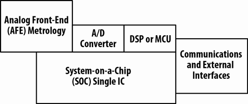
¬While a microcontroller is of central importance to the design, there are several possible levels of integration with the other functional blocks in the system. The figures below illustrate three possible architectures for a smart meter that all include analog front end (AFE) metrology, analog-to-digital converter (ADC), digital signal processor (DSP) or MCU, and communications. The first example (see Fig. 2a ) is a two-chip solution that provides flexibility for system upgrades. Second (see Fig. 2b ), is a single-chip solution with tight hardware and software integration, making it less flexible for upgrades or modification. The data transmission over the network in Fig. 2c , may be the best communication solution depending on the location.

Fig. 2a: Two-chip architecture

Fig. 2b: Single-chip architecture

Fig. 2c: Network architecture
Designing for various communications protocols
A smart meter has sensitive circuitry and most likely needs to support numerous communications protocols such as ANSI C12.18 and ANSI C12.21 in North America and IEC 61107 and IEC 62056in Europe.
As with the microcontroller architecture, no single solution has been adopted for communication between the smart meter and the utility or end user. Communication protocols vary widely based on factors such as geographical regions, location of an individual meter, what is supported by the utility servicing the area, and the maturity and longevity of those supported technologies. Wireless protocols quickly are emerging as the preferred method of connecting the networks within the grid.
Radio frequency (RF) based technology is changing the way that customers and the utility company interact with the use and sale of resources. In some cases smart meters act as the gateways for home automation, using RF signaling such as Zigbee, to communicate the resource pricing and consumption to the end user. Devices operating with 6LoWPAN, Zigbee, and RFID are examples of RF based technology connected with RF mesh networks. Cellular solutions make use of the existing cellular network to transmit metering information. Broadband over power line (BPL) has been viewed as a potential replacement of POTS and cable networks for providing broadband, though it is not available in all areas. It is desirable for a network to be capable of connecting a variety of device types, like WiMax is, since it increases the interoperability of equipment from different manufacturers following numerous protocols.
Component solutions for reliable protection
Smart meters are vulnerable to a variety of threats including line and ground voltage and transients with protection to IEC61000-4-5 requirements. Additional threats include overcurrent, overvoltage, transient voltage and frigid environments – all of which can cause serious damage to the circuitry. The communications interfaces must also be protected to ensure reliable transmission of data.
Sensing and protection circuits as well as precision resistors are a fundamental part of the smart meter electronic design. The metrology AFE revenue-grade measurements rely on the accuracy of series resistors for current sampling, scaling resistors with low temperature coefficients and low initial tolerance for voltage sampling, and current sense resistors for velocity, pressure, temperature, and flow rate measurements. For power lines, metal oxide varistors provide an optimal solution.
Current sensing and feedback
Low value resistors can provide current sensing and current feedback inside a smart meter. This solution is ideal for residential smart meters as these precise, low value resistors are very cost effective and easy to use. In an electricity meter, a resistor is placed in series with the high current electric bus bar, and the current flowing through it is calculated. The calculation is performed based on the proportional relationship of voltage and current in a resistor of known value. This current value and the instantaneous voltage are multiplied to retrieve the power consumed at any instant, and is continually monitored by the microcontroller. Resistors can be used to limit supply current to prevent damage to other components. Power resistors can also be used in a heating role to stabilize internal meter temperature in frigid environments.
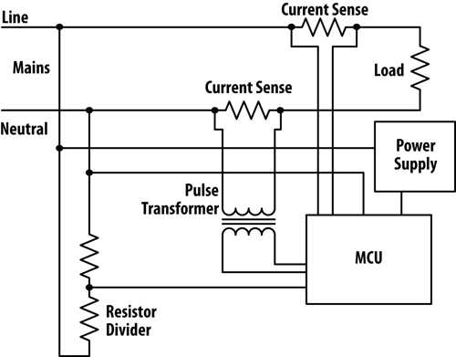
Inductance and EMI noise suppression passives are also an option in smart meter designs. Magnetics are used to help isolate current sense metrology from power conversion storage and in filtering circuits for offline and dc-subsystem bias circuitry. Inductors are used to provide RF filter tuning for these high frequency designs. Fig. 3 examines the use of current sense resistors, a pair of resistors as a divider to allow voltage measurement, and a pulse transformer at the interface of electrical mains, MCU, and power supply in an electricity meter.

Fig. 3: Resistors and magnetics in the AFE and power interfaces
Overcurrent/overvoltage protection
TVS diodes, fuses, and PTCs are viable options to protect against overcurrent and overvoltage. For example, the microcontroller will require resettable protection with a fast reaction time as a defense against surges. A fast-acting resettable fuse or PTC can handle this task. In other situations that do not require reset capability, a thin film chip fuse may be used. Diodes can provide suppression of transient voltage on the input and output signals of the microcontroller.
Communications port protection
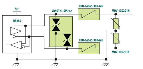
Reliability becomes even more important as utilities implement using automatic metering infrastructure (AMI) data to accomplish high-level tasks. To meet these QoS (quality of service) requirements, high reliability electric, water, or gas smart meter systems must include robust circuit protection. Whether using broadband or RF communication interfaces, a combination of overvoltage and overcurrent circuit protection devices such as TVS diodes, MOV’s, high-speed protectors, PTCs, fast-acting fuses, GDTs and magnetics will potentially be needed to address the variety of transport used to carry the information (that is, RS485, T1/E1, Zigbee, optical). Fig. 4 illustrates an RS-485 solution, which provides environment-specific ESD, EFT, and current surge transient protection. This effective combination solutions employs TVS diodes, Bourns TBU HSP (Transient Blocking Unit high-speed protector), and MOV devices.

Fig. 4: Communications protection for RS-485 transport
Smart Meters and robust circuit protection
As the smart meter market gains momentum, it is important for design engineers to consider reliable circuit protection early in the design cycle. Wireless smart meters interface with a variety of equipment, so care must be taken to ensure that the level of circuit protection from the end user to the utility company meets or exceeds the requirements of the involved standards. A smart meter generally will contain several connectivity options for maximal versatility in installation.
Selecting proven components that ensure the reliable operation and communication of smart meters is essential. Current sensing feeds directly to the processing portion of the design, and precision in this portion of the design is of paramount importance. The optimal circuit protection solution will depend on the types of processors and communication protocols used in a given installation. To help support effective circuit protection designs, Bourns provides high-quality components and a broad range of solutions that are available for integration with numerous communication standards. Bourns also provides superior customer service, and design resources such as PortNote® Solutions that illustrate sample interface solutions. For more information about Bourns® components and circuit protection solutions, visit www.bourns.com. ■
Advertisement
Learn more about Bourns


