Motor app gains efficiency with electronic control
Yesterday’s efficiency is blown away by today’s technology
BY JOE ROY
Fairchild Semiconductor
Indianapolis, IN
http://www.fairchildsemi.com
Engineers working to improve efficiency in motor drives benefit from examining the design from the system perspective, where energy savings truly makes a difference. That perspective necessarily includes power architecture, power factor, control efficiency, motor topologies and losses, and mechanical efficiencies.
Efficiency is complex
Like most performance metrics, efficiency is a complex matter of perspective. All too often, designers and regulators are uncertain how to interpret the myriad of declared efficiencies in the components of a given system.
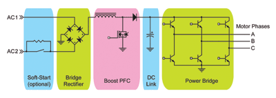
A brochure on motors might call out 85%, the gearbox datasheet 90%, and the control be labeled simply “high efficiency.” These efficiency numbers are typically selected from an ideal mode of operation that does not necessarily represent the target application’s use of each component. Figure 1 illustrates a simple motion system diagram.

Fig. 1. A typical motor control design with PFC.
For a given motor and modulation, the system’s operating efficiency is a function of supply voltage, rotational speed, load torque, and temperature. Because the specified efficiency will be valid only for a given combination of these parameters, the designer may have to ask for more efficiency data from the motor manufacturer. In variable-speed applications, the efficiency changes in various modes of operation. Similar rules apply to the belts, pulleys, gearboxes, etc. that follow the motor in a system.
Ac motor efficiency is primarily dictated by core losses, rotor/stator copper losses, and windage/friction losses. Core losses are caused by induced eddy currents and hysteresis effects in the iron rotor and stator. Because rotor and stator copper losses are driven by copper resistance as I2 R, increasing copper rotor bar size and stator wire gauge leads to lower copper losses. Core losses can be mitigated by using higher grade steel laminations and by dimensional changes that decrease flux density. Increasing copper size adds cost and limits the number of turns that can be wound on the stator. The motor operates most efficiently when the core losses and copper losses are equal, and this typically occurs between 75% and 90% of the motor’s nameplate load.
Some motor topologies are less prone to these losses than others. For example, brushless dc motors do not suffer from rotor copper losses due to their permanent magnet rotor construction. Switched or variable reluctance motors exhibit high efficiencies due in part to a lack of rotor copper losses, as they too do not conduct current through the rotor.
Although electronic drives with advanced control algorithms can dramatically improve efficiency by providing ideal power waveforms to the motor, the control has its share of efficiency issues. Control efficiency factors include soft-start losses, rectification losses, power bridge switching and conduction losses, and power factor correction losses.
Active soft-start circuits have significant losses only for about a second after power is applied to the drive. Afterward, they typically exhibit minor V*I losses as power is shunted through the active switch around the soft-start current limiter. Fractional horsepower controls usually use a relay for this purpose, reducing these losses to near zero.
Rectification is responsible for a significant portion the losses. As a typical bridge rectifier has a Vf of 1 V, these losses can easily approach 15 W on a 2-kW motor control. Lower Vf rectifiers are available at a cost premium. For ac induction and brushless dc motor controls, the power bridge typically consists of a full three-phase bridge with six diodes and six MOSFETs/IGBTs. Power bridge switching losses are a function of modulation scheme and proportional to switching frequency.
Power factor control
Last, but certainly not least, is the efficiency at which power is drawn from the ac line, the power factor (PF). Inductive and capacitive components produce repetitive, circulating currents that flow to and from the ac line. Harmonic distortions in the ac supply current can result from nonlinear elements in the motor drive.
The reactive power and harmonic currents require that the ac supply be able to provide more power than the system will actually put to good use the apparent power. The ratio of real power to apparent power is the PF, with a range of 0.0 to 1.0. A PF of 1.0 is ideal and a PF of 0.65 would require that approximately 1.5 times the application’s real power has to be available from the ac line, which comes at a significant cost to power utility companies, and utilities commonly charging a penalty to industrial customers for low PF.
Numerous power factor correction (PFC) topologies exist. Boost-PFC is the most common in motor controls, due to ease-of-implementation, and cost-effectiveness. Boost PFC circuits allow drives to easily support wide input voltage ranges (100 to 250 Vac) and to correct for low-line conditions. In a boost-PFC configuration, the dc link will typically be 370 to 400 Vdc.
The addition of PFC circuitry to a drive comes with a few advantages including a PF 0.95 or better and the decrease in dc link capacitance required due to the energy being transferred from the PFC’s inductor to the capacitor at the PFC switching frequency (> 20 kHz nominal) instead of the 120 Hz from the rectified line.
But, of course, there are PFC losses. Typical PFC circuit losses for a 1-kW motor control are around 50 W. An alternative is a configuration with MOSFETs replacing the bridge rectifier diodes, decreasing the rectifier losses.
It is time to move forward
The average motor uses up to 75 times its original purchase price in electricity during its service life, and it is time to remedy that. Fortunately, semiconductor manufacturers have made solving many of these efficiency problems much easier. Fairchild Semiconductor offers a fully integrated line of Smart Power Modules (SPM) for both motor control and PFC applications. These modules include gate drivers, MOSFETs/IGBTs, diodes, and other support components in a small package that speeds time to market.
An application example
Armed with a respect for system efficiency, we can look at a real-life application. This particular application happens to be for a livestock-breeding house ventilation system that uses 60 fans with a 52-in. blade. Each fan must move 28,000 cfm of air. Approximately 2 kW at the shaft is required to spin the blade at the required speed of 780 rpm. The fans operate for up to 8,500 hours per year.
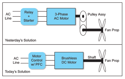
Traditionally, this application has been addressed with a three-phase, 2.5-kW ac induction motor/starter connected via relay to the ac line with an efficiency of approximately 80% and a PF of about 0.88. Because the nominal speed of these motors is around 1,750 rpm, a mechanical belt and pulley system is used to decrease the speed to that required by the fan blade (see Fig 2 ).

Fig. 2. Example application diagram for an agricultural ventilation system.
The belt and pulley mechanics have an efficiency of around 85%, requiring 2.35 kW at the motor shaft. The motor’s mediocre efficiency requires that the ac line supply 2.94 kW. The poor power factor results in the utility company having to provide up to 3.34 kW. Below a PF of 0.90, the power company calculates the low-PF surcharge as 0.75% * (0.90-PF) usage, in kilowatt-hours. The result is an annual energy billing of (8,500h * 2.94 kW * 101.5% PFC) or 25,365 kWh per fan.
The proposed solution would use a high-efficiency, 2-kW brushless motor with an efficiency of 92% at 780 rpm. The motor control would have an efficiency of approximately 97% with a PF near 0.95 across a wide range of speeds and loads. The fan is directly attached to the motor, so there are no mechanical losses, aside from the fan blade. The control is required to supply 2.17 kW to the motor. Losses in the control’s PFC and power bridge circuitry demand 2.38 kW from the ac line. The higher PF avoids any unnecessary charges from the utility company. An annual energy billing of (8,500h * 2.38 kW) = 20,230 kWh per fan is realized, yielding an annual energy savings of 5,135 kWh per fan, saving a total of $24,648 per year — a 20% reduction.
The proposed solution’s fully featured drive offers the application benefits not possible with the conventional approach, including variable-speed operation, integrated diagnostics and fault monitoring, and low-noise operation under light loads. The additional unit cost might come to about $250 to $300, with the payback easily realized six months to a year. ■
Advertisement
Learn more about Fairchild Semiconductor


